
Related Manuals for Bray 54 Series

Summary of Contents for Bray 54 Series
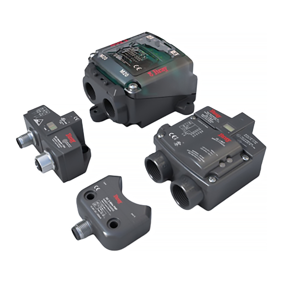
- Page 1 SERIES 54 PROXIMITY SENSORS Installation, Operation and Maintenance Manual BRAY.COM...
- Page 2 FOR MORE INFORMATION ON THIS PRODUCT AND OTHER BRAY PRODUCTS PLEASE VISIT OUR WEBSITE – bray.com...
-
Page 3: Table Of Contents
Series 54 Proximity Sensors Installation, Operation and Maintenance Manual Table of Contents 1.0 - Definition of Terms ..........2 1.1 - Hazard-free Use . -
Page 4: Definition Of Terms
• If situations transpire that are not documented in sufficient detail, please request the required information from the Bray Distributor or Representative responsible for your area. BRAY.COM... -
Page 5: Introduction
Note: The following information is intended to assist voltage after all the drops is above the minimum operating individuals with the use and support of the Bray Series 54 voltage of the last S54 in the series connection. Sensors located Proximity Sensors. -
Page 6: Activator Kit
This activation is relayed to the end user to validate valve position. Operations Bray’s S54 Sensors contain two proximity switches in a hermetically sealed housing. Location of switches are designated by a “+” or roman numerals I and II. -
Page 7: Activator
Series 54 Proximity Sensors Installation, Operation and Maintenance Manual 3.0 - Activator All S54 sensors are offered with a dedicated activators. Configurations for installation vary based on the application of the sensor and its mating components. 3.1 - Selection Activator and sensor combinations reference the following charts: Fixed Activator For Sensors PN: 540021-71104533 540022-71104533... -
Page 8: Mounting
NAMUR 30x130mm Kit No. 54119B-14800536 Capscrew 45mm Long Capscrew #10-32 1” Long applicable for size 255 Countersunk screw #10-32 1.5” Long Kit No. 54119B-14850536 Capscrew 45mm Long Capscrew #10-32 1” Long Countersunk screw M5 35mm Long Discard unused hardware BRAY.COM... - Page 9 Series 54 Proximity Sensors Installation, Operation and Maintenance Manual 3.2.1 - Fixed Activator - Rack and Pinion Actuator (continued) Size 63 to 93 Size 119 to 128 NAMUR 30x80mm NAMUR 30x80mm Kit No. 54063B-14800536 Kit No. 54119B-14800536 Capscrew 30mm Long Capscrew 45mm Long Capscrew...
-
Page 10: Adjustable Activator - Rack And Pinion Actuator
Size 160 to 255 NAMUR 30x130mm Kit No. 54160A-14800536 Capscrew 40mm Long Capscrew #10-32 7/16” Long applicable for size 255 Countersunk screw #10-32 1” Long Kit No. 54160A-14850536 Capscrew 40mm Long Capscrew #10-32 7/16” Long Countersunk screw 25mm Long BRAY.COM... - Page 11 Series 54 Proximity Sensors Installation, Operation and Maintenance Manual 3.2.2 - Adjustable Activator - Rack and Pinion Actuator continued Size 63 to 128 NAMUR 30x80mm Kit No. 54063A-14800536 Capscrew 30mm Long Capscrew #10-32 5/8” Long Kit No. 54063A-14850536 Capscrew 30mm Long Capscrew 15mm Long Size 160 to 255...
-
Page 12: Adjustable High Visibility Activator - Rack And Pinion Actuator
Size 160 to 255 NAMUR 30x130mm Kit No. 54160C-14800536 Capscrew 40mm Long Capscrew #10-32 5/8” Long applicable for Capscrew #10-32 Captive size 255 Capscrew #10-32 5/8” Long Kit No. 54160C-14850536 Capscrew 40mm Long Capscrew 15mm Long Capscrew Captive Capscrew 16mm Long BRAY.COM... -
Page 13: Hazardous Location Proximity Sensor Kit - Rack And Pinion Actuator
Series 54 Proximity Sensors Installation, Operation and Maintenance Manual 3.2.4 - Hazardous Location Proximity Sensor Kit - Rack and Pinion Actuator Size 63 to 128 NAMUR 30x80mm Kit No. 540102-12600536 Sensor 540102-71104533 Activator assembly Protective cover - Zone 2/22 Socket head capscrew #10-32X1/2, SS Kit No. -
Page 14: Scotch Yoke Actuator
3.2.5 - Scotch Yoke Actuator S98 mounting pattern matches rack and pinion size 63. Reference corresponding tables for mounting. Fixed Activator Thread Type Activator Kit PN Metric All Sizes 54063B-14850536 Adjustable Activator Thread Type Activator Kit PN Metric All Sizes 54063A-14850536 BRAY.COM... - Page 15 Series 54 Proximity Sensors Installation, Operation and Maintenance Manual Adjustable High Visibility Activator Thread Type Activator Kit PN Metric All Sizes 54063C-14850536 Hazardous Location Proximity Sensor Kit Thread Type Activator Kit PN Metric All Sizes 540102-12650536 SERIES 54 PROXIMITY SENSORS...
-
Page 16: Adjusting The Activator
Insure that the open and close activator is visible when the cover shield is installed. 5. Re-tighten the center allen head bolt locking the activator to the pinion. 6. Install the cover and mounting bolts. BRAY.COM... -
Page 17: Connections (Operation)
Installation, Operation and Maintenance Manual 4.0 - Connections (Operation) 4.4 - Cable Gland Connections Bray offers three different connections to satisfy the customer’s M20 cable gland connections are found on the following application requirements. Each sensor’s pin connection is sensors: listed in its respective technical manual. -
Page 18: Sensor Part Numbers
Series 54 Proximity Sensors Installation, Operation and Maintenance Manual 5.0 - Sensor Part Numbers Bray Part Number Electrical Output 540021-71104533 DC 3-wire PNP 540022-71104533 DC 2-wire 540032-71104533 DC 2-wire 540001-71104533 DC 3-wire PNP 540003-71104533 Intrinsically Safe 540013-71104533 Intrinsically Safe 540015-71104533... - Page 19 Series 54 Proximity Sensors Installation, Operation and Maintenance Manual SERIES 54 PROXIMITY SENSORS...
- Page 20 Bray International, Inc. All statements, technical information, and recommendations in this bulletin are for general use only. Consult Bray representatives or factory for the specific requirements and material selection for your intended 13333 Westland East Blvd. application. The right to change or modify product design or product without prior notice is reserved.
Need help?
Do you have a question about the 54 Series and is the answer not in the manual?
Questions and answers