Table of Contents
Advertisement
Quick Links
Advertisement
Table of Contents

Summary of Contents for Keithley 4200-SCS-PK3-903-01
- Page 1 Model 4200-SCS-PK3 Quick Start Guide...
-
Page 2: Safety Precautions
Observe the following safety precautions before using this product and any associated Keithley Instruments products are designed for use with electrical signals that are rated instrumentation. Although some instruments and accessories would normally be used Measurement Category I and Measurement Category II, as described in the with nonhazardous voltages, there are situations where hazardous conditions may be International Electrotechnical Commission (IEC) Standard IEC 60664. - Page 3 Chassis connections must only be used as shield connections for measuring circuits, Do not connect switching cards directly to unlimited power circuits. They are intended to be used with impedance-limited sources. NEVER connect switching cards directly to NOT as safety earth ground connections. AC mains.
-
Page 4: Power And Environmental Specifications
(note that selected parts should be purchased only through Maximum VA 1000 VA Keithley Instruments to maintain accuracy and functionality of the product). If you are Operating altitude Maximum 2000 m above sea level unsure about the applicability of a replacement component, call a Keithley Instruments Operating office for information. -
Page 5: Cd-Rom Contents
Data Sheets. Data sheets for the 4200-SCS and related CD-ROM contents equipment. This also includes brochures and other information. For additional support information, see The CD-ROM that is included with your instrument contains: http://www.keithley.com/support. Installation files for KITE. These can only be installed on the Model 4200-SCS. -
Page 6: Unpack And Inspect The Instrument
Unpack and inspect the instrument 6. Inspect the instrument for any obvious signs of physical damage. To unpack and inspect the instrument: Report any damage to the shipping agent immediately. 1. Inspect the box for damage. 2. Open the top of the box. 3. - Page 7 In the 4200-SCS-PK3 bundle, you should have received the Model 11 CS-1252 SMA male to BNC female adapters (two) 4200-SCS Semiconductor Characterization System, with: 12 CAP-31 protective caps with triaxial connectors (four) Model 4200-SMU medium power SMUs (two) 13 Model 4200-SCS User's Manual Model 4210-SMU high power SMUs (two) ...
-
Page 8: Connect The Instrument
30 V RMS and 42.4 V peak, or 60 V DC touch. Double insulation ensures the operator is still protected for equipment rated for dry locations. Keithley Instruments, Inc. even if one insulation layer fails. Refer to IEC 61010-1 for products are only rated for dry locations. -
Page 9: Install The Instrument
Install the instrument Make sure all connections are behind a locked cabinet door or other barrier. This protects the system operator from accidentally removing a connection by hand and exposing hazardous voltages. The Model 4200-SCS can be used on a bench or in a rack. Please see Use high-reliability fail-safe interlock switches to disconnect the instructions that came with your rack-mount kit if you are power sources when a test fixture cover is opened. - Page 10 If you need voltages greater than ±40 volts for testing, you must add High-voltage test fixtures, such as the Keithley Instruments LR8028, an interlock switch to the fixture. This ensures that hazardous can be used with applications that are greater than ±40 volts. The test voltages are not present when the exterior enclosure of the fixture is fixture has a safety interlock switch connected to its lid.
- Page 11 Connections for testing To connect the interlock cable: 1. Connect one end of the supplied interlock cable (part number If you are testing discrete devices, you need a test fixture that is 236-ILC-3) to the rear panel of the Model 4200-SCS. The equipped with 3-lug triaxial connectors.
- Page 12 Make keyboard and printer connections Power up the instrument 1. Connect the printer connection to the USB port or the parallel The 4200-SCS operates from a line voltage of 100 V to 240 V at a port, as needed for your printer. frequency of 50 Hz or 60 Hz.
- Page 13 ON (|) position. The instrument starts up and 2. Connect the socket of the supplied power cord to the power loads the Microsoft Windows operating system and the Keithley module on the rear panel. Interactive Test Environment (KITE) software.
- Page 14 Make connections for the I-V test If you are using the supplied test fixture, connect the MOSFET and test fixture as shown in this diagram.
- Page 15 Perform an I-V test on a MOSFET Item Description Notes To start a test: Model 4200-SCS system 1. The Project Navigator should be displayed when KITE starts. Model 4200-TRX Ultra Low Triaxial to triaxial cable that Noise PreAmp Triaxial connects 4200-PA to a test If the Project Navigator is not displayed, open the View menu Cable fixture...
- Page 16 Run the vds-id test The Definition tab, shown here, is where you define the test. KITE can run a single test or a sequence of tests. To run a single test, check the test and click it. The test should be highlighted.
- Page 17 To run a sequence of tests, check the tests you want to run, then In the following example, only one test is run. check and click the device, subsite, or project item that contains the To run the vds-id test: tests.
- Page 18 View results of the vds-id test To view data from the vds-id test, you can use the data sheets, which are similar to Microsoft Excel spreadsheets. To view the results of the vds-id test: 1. Click the Sheet tab for the test. 2.
- Page 19 Print the results of the vds-id test To export the information: 1. Open the worksheet that contains the data to be exported. You can print the Data, Calc, or Settings sheet. 2. Select Save As (in the upper right corner). To print one or a few sheets: 3.
- Page 20 View the graph for the vds-id test 2. To include a Legend and Title, select those options from the Graph Settings menu. To display the graph for the vds-id test, click the Graph tab for the test. A sample graph is shown below. In this example, there are four I-V curves –...
- Page 21 4. Select the colors for each series. 5. Click OK. The series and color information is displayed.
- Page 22 Make connections for the C-V test If you are using the supplied test fixture, connect the nMOSFET and test fixture as shown in this diagram.
- Page 23 Perform a C-V test on an nMOSFET Item Description Notes Model 4200-SCS system Model CA-447A SMA cable, male to male, 1. In the Project Navigator, select the cv-nmosfet test. This test is 100 Ω, 1.5 m located under the 4terminal-n-fet library. Model CS-1391 SMA tee adapter (female-male-female)
- Page 24 The Definition tab, shown in the next graphic, is where you define the test. In the test shown in this Definition tab, the device is connected to the CVH1 and the CVL1 terminals of the Model 4210-CVU. The default setting shows the DC bias is swept from 5 V to −5 V in 0.2 V steps, with a 1 MHz capacitance measurement taken at each step.
- Page 25 Run the cv-nmosfet test Calc: Provides data manipulation and graphing tools similar to Microsoft Excel. Settings: Information about the last test that was executed. To run the cv-nmosfet test: 1. In the Project Tree, make sure the cv-nmosfet test is checked and highlighted.
- Page 26 Print results of the cv-nmosfet test 4. Click OK. 5. From the Save As dialog box, specify a file name and path. The You can print the Data, Calc, or Settings sheet. default directory path for exporting data is C:\S4200\kiuser\export. To print one or a few sheets: 6.
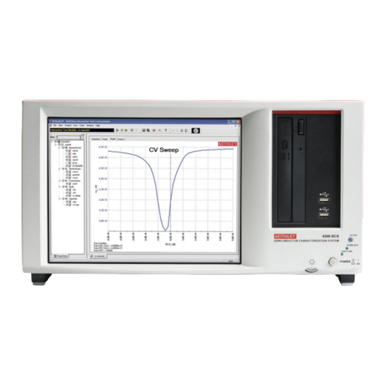
- Page 27 View the graph for the cv-nmosfet test To display the graph for the cv-nmosfet test, click the Graph tab for the test. A sample graph is shown here. In this example, the C-V curve is measured between the gate and the source/drain/bulk. Notice that the COX, CFB, and VFB parameters are extracted and displayed on the screen.
- Page 28 FAQs I cannot unplug the mini triaxial cable (Model 4200-MTRX) from the SMU The mini triaxial connector is a locking connector. To remove it, My data looks odd or is wrong. What should I do? pull the knurled part of the connector back. Verify the connections from the instrument to the test fixture.
-
Page 29: Next Steps
Application notes: Detailed applications that demonstrate specific applications. Data sheets: Technical data regarding the 4200-SCS and related accessories. Keithley Instruments website www.keithley.com for support and additional information about the instrument.
Need help?
Do you have a question about the 4200-SCS-PK3-903-01 and is the answer not in the manual?
Questions and answers