Table of Contents
Advertisement
Quick Links
Advertisement
Table of Contents

Summary of Contents for DOM WENS 800 Series
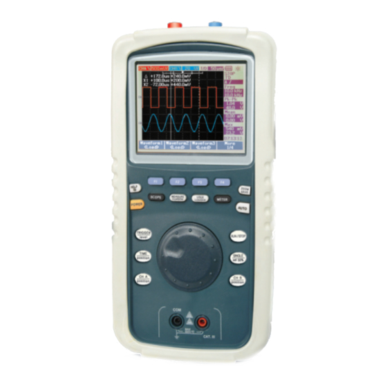
- Page 1 Hand-held Digital Oscilloscope Meter WENS 800 Series Operator’ s Manual...
- Page 2 Digital Oscilloscope Meter...
-
Page 3: Table Of Contents
Table of Contents Table of Contents 6 - 7. CURSOR Table of Contents 6 - 8. Acquire(Normal, Average, Peak) 6 - 9. MATH(DWM, FFT) 7. MULTIMETER 1. Notes for Safe Operation 7 - 1. AC and DC VOLTAGE(mV, V) measurement 1 - 1. -
Page 4: Notes For Safe Operation
Notes for Safe Operation Notes for Safe Operation Replace the battery properly Notes for Safe Operation - Replace the battery supplied by manufacturer. - Do not connect the ground wire to voltages higher than 42V Peak(30Vrms) WARNING. USE EXTREME CAUTION IN THE USE OF THIS INSTRUMENT from earth groud. -
Page 5: Safety Terms And Symbols
Notes for Safe Operation Notes for Safe Operation Safety Terms and Symbols Preventing electro-static discharge 1 - 2. 1 - 3. Technical terms which appear in this manual are listed below. CAUTION. Electro-static discharge(ESD) can result in damage to the WARNING. -
Page 6: Main Product Items And Layout
2. Main Product Items and Layout 2. Main Product Items and Layout B. Digital Multi Meter Main Product Items and Layout - High Precision, Rugged Autoranging True RMS DMM This instrument was designed to provide analysis of signals through its fast - 6000 Count with Analog Bargraph Display signal acquisition ability through the Fast Data Acquisition Unit. -
Page 7: Initial Setting Operation Before Use
3. Initial Setting Operation before use 3. Initial Setting Operation before use Initial Setting Operation before use . Function Confirmation 3 - 1 Perform the following simple steps to verify that the oscilloscope is operating For more effective operation, the instrument performs quick confirming of properly functions and provides passive probe installation and adjustment, and setting of time and date. -
Page 8: Probe Adjustment
3. Initial Setting Operation before use 3. Initial Setting Operation before use . Probe Adjustment Adjusting the time and date of the oscilloscope 3 - 2 3 - 3. Perform the adjustment function to match the probe to the input channel. This Follow the steps to adjust the time and date of the oscilloscope function must be performed each time the passive probe is first attached to the Press the... -
Page 9: Selecting Language
3. Initial Setting Operation before use 4. Front Layout Summary Front Layout Summary 3 - 6. Selecting Language Language can be selected by user A. press Front Layout 4 - 1. B. Press utility to Select 1/4 menu page(in Oscilloscope mode), 1/3 menu page(in METER mode) C. -
Page 10: Keys
4. Front Layout Summary 4. Front Layout Summary Keys 4 - 2. DUAL Function Key NOTE These Key has dual functions. upper Soft keys are located directly below the Liquid Crystal Display and perform line functions Can be entered short Position ress time. -
Page 11: Display Layout Summary
4. Front Layout Summary 5. Display Layout Summary Single Shot mode Display Layout Summary Set to 50% of Edge Trigger . press longer than 2 seconds to enter or exit the mode Display Indicators Explanation select CH A or CH B Position Position Oscilloscope... - Page 12 6. Oscilloscope Function 6. Oscilloscope Function Contrast Oscilloscope Function Adjust the screen contrast using ENCODER Switch. DISPLAY Graticule 6 - 1. Adjusts the grid shape of the waveform display section Top level menu Sub menu Mode Select type of lines, Full(10×8 lines including grid), cross Hair(cross + Type vectors, Dot sharp lines) Grid(10×8 lines) or Frames(Outer Frame lines)
- Page 13 6. Oscilloscope Function 6. Oscilloscope Function Persistence CH A, CH B 6 - 2. Position Position In persistence mode, Channel and Math function are displayed Dimmer for previous acquisition. How to change position 1. For fast change, press Position Position Key longer than 2 seconds and change position by Encoder Switch.
-
Page 14: Display(Waveform, Contrast, Graticule, Persistence)
6. Oscilloscope Function 6. Oscilloscope Function On/Off ( page 1/2) Use this function to turn the CH A(CH B) waveform on or off. In the On state, the vertical sensitivity and vertical position indication will display corresponding to the position of CH A and CH B. In the Off state, these indicators will not display. - Page 15 6. Oscilloscope Function 6. Oscilloscope Function Position to 0 (page 2/2) Note. Long time use of the unit or use in an not recommended environment may cause disagree of the channel’ s vertical position and position of the ground Use this function to set the CH A(CH B) waveform offset to 0. This is a coupling signal.
-
Page 16: A, Ch B
6. Oscilloscope Function 6. Oscilloscope Function ③ ③ Coupling (DC/AC/HF Rej./LF Rej./Noise Rej.) TRIGGER 6 - 3. As this sets the trigger source coupling, it must be selected to match the Use this function to configure settings for the trigger and trigger type. situation to observe. - Page 17 6. Oscilloscope Function 6. Oscilloscope Function Pattern Trigger Press Key and press Key to select the mode. Use this function to set each of the two trigger source High/Lows and to observe the wavelength according to the area length matching the setting. Type Sub menu Setting...
-
Page 18: Trigger
6. Oscilloscope Function 6. Oscilloscope Function For example, if the CH A signal is 150mV higher or CH B is 100mV lower in a Pulse Trigger Period which is less than 400us, configure the settings as shown below. Press Key and press Key to Select Pulse Trigger mode. -
Page 19: Trigger Mode
6. Oscilloscope Function 6. Oscilloscope Function Time (Page 1/2) Trigger Mode 6 - 4. When adjust Position, Position ICON should indicate to adjusted point. If Cursor Single shot, T’D AUTO, T’D NORMAL measurement is on Vertical axis its value is displayed. Press key to display T’D AUTO(Triggerd Auto) T’D NORM(Triggerd Time Ref... -
Page 20: Cursor
6. Oscilloscope Function 6. Oscilloscope Function - Use the method below to delete the measured value. CURSOR 6 - 7 . Press key longer than 2 seconds to enter/exit mode Classification Sub menu Function Mode Y1 / Y2 / Y1, Y2 Y-Cursor Press key and select... - Page 21 6. Oscilloscope Function 6. Oscilloscope Function A. Y-Cursor B. X-Cursor A cursor parallel to the vertical Axis will appear to measure the voltage. A cursor parallel with the horizontal axis will appear on the display to measure the voltage value at the desired point. Select the desired signal to measure between CH A/CH B from the source menu.
-
Page 22: Acquire(Normal, Average, Peak)
6. Oscilloscope Function 6. Oscilloscope Function Normal ACQUIRE Press enter Acquire mode. 6 - 8. Use this function to observe the signal from the ADC unchanged. Upper Level Sub menu Explanation Menu Average Averages and displays the waveforms collected from the oscilloscope high Mode Normal, Average, Peak speed data collection terminal. - Page 23 6. Oscilloscope Function 6. Oscilloscope Function Roll, Trig - Roll, Trigger Use this function to observe the signal from the ADC unchanged. Roll Data in continuous waveform moves from right edge of display to left edge of the display. This allows to observe the changes of waveform movement in low frequency area ( like as potentiometer adjustment) .
-
Page 24: Math(Dwm, Fft)
6. Oscilloscope Function 6. Oscilloscope Function FFT (Fast Fourier Transform)(model 840, 860 only) MATH 6 - 9. (Model 820 is not available) Calculates and updates the FFT to determine the properties of the signal Enter and press key. frequency on the screen in real time. OFF : erase all data or math - Source : CH A/CH B... -
Page 25: Multimeter
7. Multimeter 7. Multimeter METER Display Multimeter Note. All multimeter measurement works in AUTO RANGING Mode. To change to MANUAL RANGING, press key to enter or exit. AC and DC VOLTAGE(mV, V) measurements 7 - 1. Enter volt WARNING. Risk of electrocution. The probe tips may not be long enough to contact the live parts inside some 240V outlets for appliances because the contacts are recessed deep in the outlets as a result, the reading may show 0 volts when the outlet actually has voltage on it. -
Page 26: Resistance Measurement
7. Multimeter 7. Multimeter DIODE test 7 - 3. RESISTANCE measurements 7 - 2. WARNING. To avoid electric shock, do not test any diode that has voltage on it. WARNING. To avoid electric shock while taking any resistance measurements, disconnect power to the unit under test and discharge all capacitors, remove ①... -
Page 27: Continuity Check
7. Multimeter 7. Multimeter CONTINUITY check CAPACITANCE measurements 7 - 4. 7 - 5. WARNING. To avoid electric shock, disconnect power to the unit under test and WARNING. To avoid electric shock, never measure continuity on circuits or wires that discharge all capacitors before taking any capacitance measurements. -
Page 28: Zoom/Save
8. ZOOM/SAVE 8. ZOOM/SAVE Main ZOOM/SAVE Use this function to return to the previous state before magnification. The horizontal scale factor returns to its original level. 8-1. Zoom Type Menu Function MAIN Return to Normal before magnified Magnify Zoom Waveform magnified by the waveform ZOOM Move function. - Page 29 8. ZOOM/SAVE 8. ZOOM/SAVE Window ON/OFF 8-2. SAVE Use this function to view or remove the zoom area selection bar. Press Press longer than 2 second of the Key to enter SAVE mode. open the window and set the zoom area through the use of the ENCODER switch Upper Level Sub menu...
- Page 30 8. ZOOM/SAVE 8. ZOOM/SAVE A. When USB memory is not connected RECALL Factory Setup: Use this function to save or load the desired waveform or settings to the unit’ s internal memory. Up to 10 waveforms and 10 settings can be saved. To return to initial Factory setup status, move Encoder Switch to If press key,...
- Page 31 8. ZOOM/SAVE 8. ZOOM/SAVE UPDATE When select Waveform SAVE/Recall Erase saved data and changed to present setting: SAVE move to √ mark area where to update by Encoder switch. If press Save/Recall Waveform , Save/Recall pop up window shows. Press key, Pop Up window shows “Which function select ?”...
- Page 32 8. ZOOM/SAVE 8. ZOOM/SAVE RECALL UPDATE Select the SAVED data with mark by Encoder switch Press F1 key. Pop Up Erase saved data and changed to present setting window shows “Which function select ? Update Erase” then select the move to √ mark area where to update by Encoder switch. Desired menu by Encoder switch and press the Switch.
- Page 33 8. ZOOM/SAVE 8. ZOOM/SAVE B. When Flash memory Port is connected (optional feature) Use this function to directly store or load data from USB flash memory. There are SVW, BMP selections. Move cursor to the desired character location by Encoder switch and press SELECT.
-
Page 34: Auto
9. AUTO 10. DATA LOGGER AUTO DATA LOGGER USER LOGGER AUTO function in SCOPE mode Press USER key longer than 2 seconds to enter or exit the function LOGGER Data Logging function is for Multimeter in Autoranging mode. Automatically adjust Volts/div, Time/div, Trigger Configure at best condition. Set Time/div by counting Trigger Pulse and find Volts/div and select which The Data Logger plots the measurement values versus time base in graph channel is base of Time/div. - Page 35 10. DATA LOGGER 10. DATA LOGGER Max.Min.Average Press key to select Max.Min,Average. Max, Min value is the last measurement Max. Min value and Average value is the arithmetic average value of the last 8 readings. The real time minimum and maximum measurements are displayed Along with the recorded data.
-
Page 36: External Layout Summary
11. External Layout Summary 11. External Layout Summary External Layout Summary 11 - 2. USB Flash Memory port Press key and enter Utility. Select menu 1/4 page 11 - 1. USB COMMUNCATIONS (when Oscilloscope mode) or menu 1/3 page (when Meter, Logger mode) .Then, press USB ON/OFF key and select “ON”... -
Page 37: Tilt Stand
11. External Layout Summary 11. External Layout Summary 11 - 3. AC Power 11 - 5. Battery Replacement - Input : 100V ~ 240VAC free voltage ① Disconnect the test leads from any circuit being measured. - Output : DC12V/2A 50/60Hz (model 820, 840, 860) ②... -
Page 38: Product Standards And Specifications
12. Product Standards and Specifications 12. Product Standards and Specifications Product Standards and Specifications HORIZONTAL MODEL 800X 800Z OSCILLOSCOPE 50 ns/div~50 s/div 10ns/div~50 s/div 50 ns/div~50 s/div SEC/DIV Range MODEL 800X 800Z Time Base Accuracy ±0.01% 20MHZ 40MHZ 60MHZ 100MHZ 200MHZ pre-Trigger : 20div max. - Page 39 12. Product Standards and Specifications 12. Product Standards and Specifications TRIGGER ACQUISITION Sources ChannlA and B MODEL 800X 800Z Real-Time 200MS/s single channel, 1 GS/s Single Channl, Modes Auto, Normal, Single 100MS/s per channel 500MS/s per Channel Advanced Selections Edge, Pulse, Pattern, Video Sample Rate Edge Trigger on arising or Falling edge of any source...
- Page 40 12. Product Standards and Specifications 12. Product Standards and Specifications FUNCTIONS CAPACITANCE Save/Recall 10Waveforms, 10 Settings Range 60nF - 300uF Zoom Direct Time/Volt conversion Accuracy ±(2.0%+10 digits) XY Mode X Axis Channel Input - YAxis Channel Input OTHER MEASUREMENTS Diode Check Accuracy:2% MULTIMETER Continuity...
- Page 41 12. Product Standards and Specifications 12. Product Standards and Specifications USABILITY & SUPPORTABILITY STANDARD ACCESSORIES USB Flash memory host Option DESCRIPTION QUANTITY USB for PC Interface USB2.0 Client Rechargeable Battery Pack 8B(for 820/840/860)or 8BX(for 800X/800Z) Self Test Power adapter and charger Power on Test, Diagnostic Test Failure message, Calibration Abort, Calibration Factor, User’s Manual in CD or Printed Manual...
- Page 42 13. REVISIONS & REMARK REVISIONS & REMARK...
- Page 43 WENS WENS Precision Co.,Ltd 203-701, Bucheon Techno-Park 192 Yakdae-Dong, Wonmi-Gu, Bucheon City, Gyunggi-Do, Korea Tel. 8232-621-1500 Fax. 8232-621-1505 e-mail. wens@wens.co.kr www.wens.co.kr Printed in Korea...
Need help?
Do you have a question about the WENS 800 Series and is the answer not in the manual?
Questions and answers