Table of Contents
Advertisement
Quick Links
Advertisement
Table of Contents

Summary of Contents for PMK PKT 520A
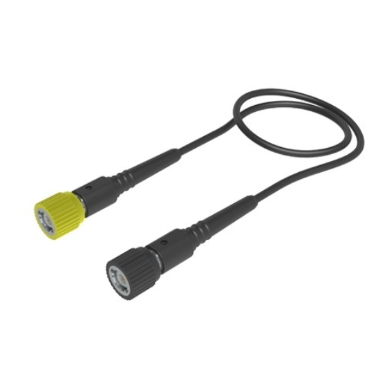
- Page 1 PKT 520A High Impedance Passive Cable Divider Instruction Manual...
-
Page 2: Warranty
(including damages for loss of profits, loss of business, loss of use or data, interruption of business and the like), even if PMK GmbH has been advised of the possibility of such damages arising from any defect or error in this manual or product. -
Page 3: Declaration Of Conformity
Your help and efforts are required to protect and keep clean our environment. Therefore return this electronic product at the end of its life either to the Service Department of PMK Mess- und Kommunikationstechnik GmbH or take care of separate WEEE collection and professional WEEE treatment yourself. - Page 4 IEC Measurement Categories PKT520A Definitions and Examples (Clause 6.5.2) Measurement Category I Definition: Measurement category I is for measurements performed on circuits not directly connected to a mains supply. Examples: Measurements in circuits not derived from a mains supply and specially protected ( internal ) circuits derived from a mains supply.
- Page 5 IEC Pollution Degrees PKT520A Definitions (Clause 3.5.6 ) Pollution Degree 1 No POLLUTION or only dry, non conductive POLLUTION. NOTE The POLLUTION has no influence. Pollution Degree 2 Only- non conductive POLLUTION. Occasionally, however, a temporary conductivity caused by condensation must be accepted. Pollution Degree 3 Conductive POLLUTION occurs or dry, non-conductive POLLUTION occurs which becomes conductive due to condensation which is to be expected.
-
Page 6: Safety Information
Safety Information PKT520A To avoid personal injury and to prevent fire or damage to this product or products connected to it, review and comply with the following safety precautions. Be aware that if you use this probe assembly in a manner not specified the protection this product provides may be impaired. - Page 7 Handling PKT520A Note that the probe cable is a sensitive part of the probe. Do not damage through excessive bending or pulling. Avoid mechanical shock to this product in general to guarantee accurate performance and protection. Maintenance Cleaning To clean the exterior of the probe use a soft cloth moistened with either distillated water or isopropyl alcohol. Before use allow the probe to dry completely.
-
Page 8: Electrical Specifications
300 V rms CAT II Pollution Degree Voltage Derating Typical voltage derating PKT520A Typical Voltage Derating PKT 520A Measurement Category I Note that the max. input voltage rating of the cable divider decreases as the frequency of the applied signal increases. -
Page 9: Electrical Characteristics
Compensation Range 10 pF - 40 pF Input coupling of the measuring instrument 1 MΩ AC / DC Input Impedance Typical Input Impedance PKT 520A Typical input impedance PKT520A 100M Note that the Input Impedance of the 100K cable divider decreases as the frequency of the applied signal increases. -
Page 10: Adjustment Procedures
Adjustment Procedures PKT520A The cable divider can be adjusted for low frequency (LF) compensation and for high frequency (HF) compensation. LF Compensation LF needs to be adjusted when the probe is connected to the oscilloscope input the first time. LF compensation matches the probes cable capacitance to the oscilloscope input capacitance. - Page 11 Adjustment Procedures PKT520A HF Compensation HF needs to be adjusted when the cable divider is connected to the scope input the first time. We recommend to use the following equipment for proper HF compensation: Rectangular wave generator with a rise time faster than 700 ps, 50 Ohm feed-through. HF adjustment is performed by connecting the cable divider to the rectangular wave generator.
-
Page 12: Scope Of Delivery
Accessories PKT520A Scope of Delivery The following items are included in the scope of delivery. Please check the delivery for completeness. If any item is missing, send a message to our service department and we will send you this item immediately. Item Adjustment Tool T Coding Rings (Set) 3x4 colors...
Need help?
Do you have a question about the PKT 520A and is the answer not in the manual?
Questions and answers