Table of Contents
Advertisement
Advertisement
Table of Contents

Related Manuals for Tempo Communications Sidekick Plus


Summary of Contents for Tempo Communications Sidekick Plus
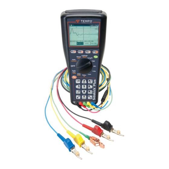
- Page 1 INSTRUCTION MANUAL Sidekick Plus ® Test Set Read and understand all of the instructions and safety information in this manual before operating or servicing this tool. Register this product at www.TempoCom.com © 2019 Tempo Communications Inc. 52063747 REV 5 12/19...
-
Page 3: Table Of Contents
Sidekick Plus Test Set ® Table of Contents INTRODUCTION ............5 Description ............5 Safety ..............5 Purpose of this Manual ........5 Test Lead Terminology ......... 6 IMPORTANT SAFETY INFORMATION ......8 Measurement Categories ........9 COMPONENTS ............10 Base Unit ............ - Page 4 Testing Notes .......... 106 APPENDIX F – ACRONYMS ........107 All specifications are nominal and may change as design improvements occur. Tempo Communications Inc. shall not be liable for damages resulting from misapplication or misuse of its products. Sidekick is a registered trademark of Textron Innovations Inc.
-
Page 5: Introduction
Observe all of the safety information provided. Purpose of this Manual This instruction manual is intended to familiarize all personnel with the safe operation and mainte- nance procedures for the Tempo Communications Sidekick Plus Test Set. ® Keep this manual available to all personnel. -
Page 6: Test Lead Terminology
Sidekick Plus Test Set ® Test Lead Terminology This manual assumes the North American terminology use of “Tip” (T), “Ring” (R), and “Ground” (G) for the test leads. This terminology dates back to the days of jack & plug fields where the names were literal, the “tip” being the end terminal, the “ring”... - Page 7 Sidekick Plus Test Set ® IMPORTANT SAFETY INFORMATION SAFETY ALERT SYMBOL This symbol is used to call your attention to hazards or unsafe practices which could result in an injury or property damage. The signal word, defined below, indicates the severity of the hazard.
-
Page 8: Important Safety Information
Sidekick Plus Test Set ® IMPORTANT SAFETY INFORMATION Explosion hazard: Do not operate in an explosive atmosphere. Failure to observe this warning could result in severe injury or death. Electric shock hazard: • Do not expose this unit to rain or moisture. •... -
Page 9: Measurement Categories
Sidekick Plus Test Set ® Measurement Categories These definitions were derived from the international safety standard for insulation coordination as it applies to measurement, control, and laboratory equipment. These measurement categories are explained in more detail by the International Electrotechnical Commission; refer to either of their publications: IEC 61010-1 or IEC 60664. -
Page 10: Components
Sidekick Plus Test Set ® COMPONENTS The Sidekick Plus kit contains the following: ® • Base unit • Primary test leads (red, green, black) • Main carrying case • Accessory carrying case • Instruction Manual • Secondary test leads (blue and yellow) •... -
Page 11: Base Unit
Sidekick Plus Test Set ® Base Unit The front of the base unit is divided into three major sections: an LCD screen with four function keys, a rotary selector knob, and a standard keypad. The front also contains connectors for the primary test leads (red, black, and green) and for the secondary test leads (yellow and blue). - Page 12 Sidekick Plus Test Set ® Rotary Selector Knob The center of the base unit contains the rotary selector knob. The OFF position is at the nine o’clock position. Starting clockwise from the OFF position, the following positions are available for selection: •...
- Page 13 Sidekick Plus Test Set ® Keypad The keypad is the standard telephone keypad with the following additions: • Fn key is used to enter the secondary function modes. • O (Back) key is used to exit the current menu page. •...
-
Page 14: Operation
Sidekick Plus Test Set ® OPERATION Note: Fully charge the batteries for at least 8 hours prior to first use. Electric shock hazard: For safety and measurement accuracy reasons do not connect to the measurement leads while using USB ports or battery charger. Failure to observe this warning could result in severe injury or death. -
Page 15: Function Keys
Sidekick Plus Test Set ® Function Keys F1 HELP Access the HELP screen by pressing and holding the Fn key. Then press the F1 HELP function key. This screen displays instructions directly related to the position of the rotary selector knob. If the knob is in the VOLTS position, the instructions explain how to obtain a voltage measurement. - Page 16 Sidekick Plus Test Set ® F3 ANALOG METER All measurements are displayed in digital form. However, because many users prefer to use an analog format, the Sidekick Plus test set provides the techni- ® cian with an analog meter. Press and hold the Fn key. Then press the F3 ANALOG key.
- Page 17 Sidekick Plus Test Set ® F4 MAIN MENU To access the MAIN MENU, press and hold the Fn key. Press the F4 MAIN MENU key. The menu may be accessed directly from all modes except TDR, RFL, Autotest, and Impulse Noise. Pressing the appropriate number key on the keypad accesses each section of the menu.
-
Page 18: Measuring Voltage
Sidekick Plus Test Set ® Measuring Voltage The first test available on the rotary knob is the VOLTS test. This position allows the technician to test both AC and DC volts. The Volts menu allows the technician to jump between AC and DC. 1. - Page 19 Sidekick Plus Test Set ® Note: Normally there should never be any measurable amount of AC voltage on a twisted pair. If AC voltage is detected on a telephone pair, this problem must be isolated and corrected immediately because AC voltage may affect other tests.
- Page 20 Sidekick Plus Test Set ® Move the rotary knob to the VOLTS position. The LCD screen now displays DC voltage on a single pair tip-to- ring. “T-R” is displayed in the upper left corner. • F1 T-G displays tip-to-ground; “T-G” now in the upper left corner and “T-G”...
- Page 21 Sidekick Plus Test Set ® 3-Lead To check the DC voltage on 3-lead, press the F3 3-Lead key. DC voltage is displayed from the tip- to-ring, tip-to-ground, and ring-to-ground in sequence, with the active measurement in bold. Press the F3 3-Lead key to return the screen to the single pair DC menu.
-
Page 22: Measuring Loop Current
Sidekick Plus Test Set ® Measuring Loop Current Loop current is inversely proportional to resistance. If a pair’s loop resistance increases, its current decreases. Measuring the loop current, therefore, provides an important indicator if there are any resistance problems on an active pair. To measure loop current, perform the following steps: 1. -
Page 23: Stress Balance Measurements
Sidekick Plus Test Set ® 3-Lead To access the 3-lead screen, press F3 3-Lead. The initial measurements of the tip-to-ring and ring-to- ground occur when the LCD screen first appears. The measurements are shown in sequence, with the active measurement in bold. Return to the Single Pair screen by pressing the F3 3-Lead key. - Page 24 Sidekick Plus Test Set ® Stress Test Effectiveness The stress test identifies capacitive imbalances (i.e., unequal conductor lengths) and DC problems (i.e., crosses and grounds) anywhere along the length of a dry or idle-working pair. The STRESS measurement on the Sidekick Plus test ®...
-
Page 25: Longitudinal Balance
Sidekick Plus Test Set ® Longitudinal Balance Longitudinal Balance is a measurement of a pair’s quality. A pair having a high balance value is less sus- ceptible to noise and interference. Low balance values can be associated with “hum” on voice circuits, and with impulse noise causing intermittent DSL service. -
Page 26: Ground Resistance Test
Sidekick Plus Test Set ® Ground Resistance Test Ground resistance testing is useful when evaluating whether a station, or premise, ground is sufficient. The reading is a direct indication of the ground integrity and measures the earth resistance. High readings are potentially due to short ground rods, poor ground connections, etc. -
Page 27: Leakage/Resistance
Sidekick Plus Test Set ® 7. Press F1 Start to read the earth ground resistance of the ground rod. Less than 25 Ω is typically considered good. Leakage/Resistance LEAKAGE The LEAKAGE measurement applies 150 VDC to the pair under test to detect intermittent resistance faults that normal VOM tests cannot detect. - Page 28 Sidekick Plus Test Set ® To change the measurement, use the following function keys: • F1 T-G to access tip-to-ground measurement. • F2 R-G to access ring-to-ground measurement. • F3 REV to reverse polarity. • F4 selects between 3 ranges: R x 1k measures up to 1MΩ...
- Page 29 Sidekick Plus Test Set ® 3-Lead Press F3 3-Lead to access resistance measurements of all three leads in sequence on the LCD screen. The active measurement will be in bold. To check the resistance measurement of a single pair, press the F3 Single Pair key to return to the single pair LCD menu.
-
Page 30: Measuring Cable Length
Sidekick Plus Test Set ® Measuring Cable Length The LENGTH selection measures the distance to an open, mutual capacitance as well as the conductor to ground capacitance of the pair. Note: This Sidekick Plus test set can subtract the test ®... - Page 31 Sidekick Plus Test Set ® 3-Lead To obtain a 3-lead measurement, press F3 3-Lead while on the Length menu. The length or capacitance measurement is displayed from the ring-to-tip, tip-to- ground, and ring-to-ground in sequence, with the active measurement in bold. Return to the Single Pair screen by pressing the F3 3-Lead key.
-
Page 32: Time Domain Reflectometer (Tdr)
Sidekick Plus Test Set ® Time Domain Reflectometer (TDR) The TDR position of the rotary knob converts the Sidekick Plus test set into a time domain reflectometer ® that sends out pulses of energy and then measures the time interval of the reflections. The way energy is reflected and the amount of the energy reflected indicate the condition of the cable. - Page 33 Sidekick Plus Test Set ® Cable Type Use the keypad arrow keys (2 and 8) to scroll through the cable types. Once the correct one has been high- lighted, press the F4 key to exit. If the cable type is not listed, the user may create a new cable type by accessing the MAIN MENU (Fn-F4) and selecting 2 Cable Config.
- Page 34 Sidekick Plus Test Set ® Zoom The zoom feature allows the user to get a closer look at the TDR trace. It displays the following controls: • 1 (Zoom Out) gives the user a broader look at the data over a larger range. •...
- Page 35 Sidekick Plus Test Set ® Load Coils Note: Load coil waveforms look very similar to an open waveform (see previous illustration). Typically, the load coil is located at its appropriate spacing, depending on the loading scheme being used. TDR will not be able to see past the load coil.
- Page 36 Sidekick Plus Test Set ® Water 1. Press F4 More Cable until the reflection is displayed. 2. Use the up (2) and down (8) arrows keys to adjust the waveform height. 3. Use the left (4) and right (6) arrows to move the cursor to the beginning of the wet section (“A”...
- Page 37 Sidekick Plus Test Set ® 6. Press the right (6) key until the desired type is high- lighted, or the keypad number key of the desired type: • Test Pair: Red and black leads. • Test Pair/Reference Pair: Both test (red/black) and reference (yellow/blue) test leads are displayed.
- Page 38 Sidekick Plus Test Set ® Saving a Trace The Sidekick Plus test set can save TDR traces to its ® internal memory. The user can later either display them on the unit or download them to a PC with the Tempo Record Manager.
-
Page 39: Resistance Fault Locator (Rfl)
Sidekick Plus Test Set ® Deleting a Saved Trace The Sidekick Plus test set can delete a previously ® saved TDR trace from the unit. To delete a saved trace: 1. From the MAIN MENU, press 9 (Save) to enter the Save/Recall menu. - Page 40 Sidekick Plus Test Set ® One Good Conductor If two good conductors are not available, the RFL can work in 3-lead mode with the yellow lead unused. If 3-lead mode is used, the blue lead conductor must be in the same cable as the red. Use the strap included in the accessories case to short the two conductors together at the far end.
- Page 41 Sidekick Plus Test Set ® The next two displays illustrate a 3-wire connection and a 4-wire configuration if the yellow lead is con- nected to the cable. Sidekick Plus test set connections are on the left; ® the strap is on the right. The resistance of the fault is highlighted.
- Page 42 Sidekick Plus Test Set ® Changing Gauge and Temperature Press F2 Setup. 1. Use the up (2) and down (8) arrow keys to adjust temperature displayed at the top in the center. 2. Once the correct temperature is displayed, press F2 Setup again.
- Page 43 Sidekick Plus Test Set ® Special Connection of Leads/Strap On shorts, the black clip is connected to the other side of the short. On a contact fault, the black clip is connected to the other side of the contact (see illustration below). On an earth, the black clip is connected to the cable shield or earth (see illustration below).
- Page 44 Sidekick Plus Test Set ® K-Test (two faulted wires) To begin the K-Test: 1. Move the rotary knob to the RFL position. 2. Connect leads: • Red lead: Connects to one faulted wire (Fault 1). • Black lead: Connects to the other faulted wire (Fault 2).
- Page 45 Sidekick Plus Test Set ® 4. Strap the wires connected to the Black and Red test cords as instructed by the Sidekick Plus test ® set, and then press F1 Next. The test set will then measure and display the fault location and the distance to the strap.
-
Page 46: Checking For Load Coils
Sidekick Plus Test Set ® Checking for Load Coils To check for load coils, perform the following steps: 1. Connect the test leads: black to tip, red to ring, and green to ground. 2. Move the rotary knob to the COILS position. The graph represents the impedance of the line. - Page 47 Sidekick Plus Test Set ® 2. Press F1 Save. Enter a name for the trace with the keypad. Press a key repeatedly to rotate through the letters and numbers of the key. 3. Press F4 Done when complete. 4. Use the Tempo Record Manager to download the traces to a PC.
-
Page 48: Measuring Circuit Loss
Sidekick Plus Test Set ® Measuring Circuit Loss The CKT LOSS selection measures the signal attenu- ation on the pair from the central office (C.O.) to the point of test. Values less than 0 dB display as a nega- tive number. The test requires a 0 dBm (one milliwatt in 600 ohm), 1004 Hz test tone transmitted from the C.O. - Page 49 Sidekick Plus Test Set ® Specifications for the circuit loss measurements are as follows: • Range: +3 to –70 dB • Resolution: 0.1 dB • Accuracy: ±0.5 dB Phone Book Pressing F2 Phone Book on the Ckt Loss main screen displays frequently used phone numbers dialed for circuit loss.
-
Page 50: Measuring Circuit Noise And Power Influence (Pi)
Sidekick Plus Test Set ® Measuring Circuit Noise and Power Influence (PI) The circuit noise and power influence measurements are performed on the same display. Power Influence The power influence measurement specifically identifies electromagnetic interferences (EMI) from external sources (mainly power lines). When this test is activated, the Sidekick Plus test set shorts ring and ®... - Page 51 Sidekick Plus Test Set ® 4. Use the down (8) key to highlight the “Noise” line. The noise reading appears immediately followed by the balance, which the test set calculated. Note: Once connected to the quiet line, the user can toggle between the noise and power influence mea- surements.
- Page 52 Sidekick Plus Test Set ® Voiceband Spectrum Analyzer A spectral graph for analysis of power influence and noise may be accessed through the NOISE/PI function. This graph will be useful in determining the types of noise, frequency of the noise in the voiceband, and the amplitude at each frequency.
- Page 53 Sidekick Plus Test Set ® Noise Spectral Analysis This measurement shows the background Noise on the circuit across the voiceband up to 4 kHz. To use the Noise Spectrum Analyzer, perform the following: 1. Connect the test leads: black to tip, red to ring, and green to ground.
-
Page 54: Automatic Test
Sidekick Plus Test Set ® Automatic Test The AUTOTEST selection checks most of the tool’s tests and measurements by comparing them to tolerances set by the Autotest configuration selected. It is a quick check to qualify a line against specific standards. The AUTOTEST runs through all the tool’s tests except the TDR, impulse noise, ground resistance, and RFL. -
Page 55: Autotest With Fed
Sidekick Plus Test Set ® 3. Insert a USB flash drive into the larger USB port at the top of the test set. The USB symbol should appear in the top of the Sidekick Plus display ® 4. Press F2 USB Save to save the test result in XML format to the USB flash drive. - Page 56 Sidekick Plus Test Set ® After the test has completed, press F1 Show Graph to show the Wideband Slope graph. Use the left (4) and right (6) arrows to move the cursor. The Loss and frequency values are shown in the upper right corner of the graph.
-
Page 57: Tools Menu
Sidekick Plus Test Set ® TOOLS MENU To access the TOOLS MENU, rotate the rotary knob to AUTOTEST/TOOLS, and then press the Fn key. 1 Dial Pressing the 1 key allows the Sidekick Plus test set to ® make phone calls by dialing numbers on the keypad. 2 Phone Book When the 2 key is pressed, the phone book is accessed. -
Page 58: Impulse Noise (Optional)
Sidekick Plus Test Set ® 4 Impulse Noise (optional) Refer to “Appendix B”. 5 R/D Calculation Pressing the 5 key provides the technician with a resistance vs. distance calculator. 1. The up (2) and down (8) arrow keys highlight the various possibilities. -
Page 59: Caller Id
Sidekick Plus Test Set ® Select tone type with the right (6) key while the “Tone Type” field is highlighted. Choices include the following: • Metallic: Ring to tip • Loss reference tone: Ring to tip with output level control; only use on dry lines •... -
Page 60: Tools Menu
Sidekick Plus Test Set ® TOOLS MENU – PAGE 2 1 FED Control The FED Control menu provides a means to perform a single test mode with the aid of the FED. 1. Selecting a FED Type: • Press F4 to view the available FEDs. •... -
Page 61: Modem Update
Sidekick Plus Test Set ® • Short/Ground Pair – The FED shorts A (TIP), B (RING) and E (GROUND). When in this mode, resistance balance can be measured. • Longitudinal Balance – The FED places an IEEE 455-1985 Longitudinal Balance Termination on the pair. -
Page 62: Main Menu
Sidekick Plus Test Set ® MAIN MENU The MAIN MENU may be accessed from any test screen except the TDR, RFL, and Autotest. To access the MAIN MENU, press and hold the Fn key. Press the F4 key. Pressing the appropriate number key on the phone keypad accesses each section of the menu. - Page 63 Sidekick Plus Test Set ® To move to the next options menu, select F3 Next. If no more changes are required, press the O (Back) key. The second Device Setting screen provides the follow- ing options to the user. Each option can be reached by using the up (2) or down (8) buttons: •...
- Page 64 Sidekick Plus Test Set ® Date/Time Setting Screen The Date/Time Setting screen provides the user with various time-related options. Each option can be reached by using the up (2) or down (8) buttons: • System Date: Displays the current system date. To modify the date, press F1 Edit.
- Page 65 Sidekick Plus Test Set ® • Backlight Timer: This option allows the user to select the backlight timeout for the system. If the unit is inactive for the amount of time given by this timer (meaning no keypress or rotary switch events), the screen backlight will be turned off to conserve battery power.
-
Page 66: Cable Config
Sidekick Plus Test Set ® 2 Cable Config Pressing 2 while on the MAIN MENU screen accesses the Cable Configuration screen. This screen allows the user to make any one of a number of changes or addi- tions to the cables configured for use in TDR, RFL, and the R-D calculator. -
Page 67: Autotest Config
Sidekick Plus Test Set ® Multi-Gauge Cable The cable being tested may be constructed of two or more sections of different cable types. The test set will use the Multi-Gauge cable table when computing the distance results in the RFL test. •... -
Page 68: About
Sidekick Plus Test Set ® Autotest configurations allow Autotest to be customized for different test scenarios. Other configurations may be downloaded into the unit through the Tempo Record Manager. • F1 Edit to make changes to test thresholds and select which test is to be included (only the CustomScript may be edited by the unit). -
Page 69: Maintenance
Sidekick Plus Test Set ® MAINTENANCE Cleaning If the Sidekick Plus test set requires cleaning, mix a ® solution of mild detergent and warm water. 1. Dip a soft, lint-free rag into water. 2. Wring excess water from the rag until it is slightly damp. - Page 70 Sidekick Plus Test Set ® Battery Warning When the batteries are significantly depleted and could cause the unit to fail during a test, a low battery warning appears on the screen each time a test is attempted. If the unit is kept on with low batteries, the low battery warning flashes for one minute and then the unit turns itself off.
- Page 71 Sidekick Plus Test Set ® REPLACEMENT PARTS AND ACCESSORIES Do not attempt to replace or repair any of the components inside the main body of the Sidekick Plus ® test set. If your test set requires service, please contact Tempo at 1-800-642-2155 for the location of the nearest authorized repair and calibration facility.
-
Page 72: Specifications
Sidekick Plus Test Set ® SPECIFICATIONS Sidekick Plus Test Set ® Dimensions: 279 x 121 x 76 mm (11 x 4.75 x 3 in); 305 x 140 x 114 mm (12 x 5.5 x 4.5 in) (in soft case) Weight: 1.4 kg (3 lb) (includes Li-ion battery pack, soft case, and test leads) Weight (1155-5012 and 1155-5013): 1.8 kg (4 lb) (includes Li-ion battery pack, soft case, and test leads) - Page 73 Sidekick Plus Test Set ® 0 to 99 Ω • Resolution: 0.1 Ω • Accuracy: ±3% or 1 Ω 100 Ω to 100 MΩ • Resolution: 4 digits • Accuracy: ±3% Distance to Open (Meter) Range: 0 to 30 km (0 to 100,000 ft) 0 to 30 m (0 to 99 ft) •...
- Page 74 Sidekick Plus Test Set ® K-TEST • Distance measurement accuracy: 0.5% of DTS, ±0.5 Ω • Maximum fault resistance: 20 MΩ • Distance range: 0 to 20 km (0 to 65 kft) • Fault1 / Fault2 > 2 • LoopR * 100 < Fault1 + Fault2 Tone •...
-
Page 75: Warranty
Sidekick Plus Test Set ® WARRANTY General Provisions Seller warrants to Buyer that products furnished hereunder will be merchantable, free from defects in design, material, and workmanship, fit and sufficient for the purposes intended by Buyer, free from all liens and encumbrances and will conform to and perform in accordance with the specifications set forth in the Agreement for a period of One Year, commencing with... -
Page 76: Specific Warranty Provisions
Extended Warranty Extended warranty is available at the buyer’s option. Warranty on Repaired Products Tempo Communications Inc. offers a 90-day warranty against defects in material or workmanship for repaired products. Extended repair warranty may be avail- able for select customers and is negotiated by sales department. -
Page 77: Appendix A: Startup
Sidekick Plus Test Set ® APPENDIX A: STARTUP When the Sidekick Plus test set is used for the first ® time, the user has the option to set several options. These options are described on each of the following screens. The first screen allows the user to select the display language. - Page 78 Sidekick Plus Test Set ® The third option selects the cable pair identification. Select either “Tip/Ring” or “A/B”, and then press F4 to continue to the next option. The fourth option selects the temperature unit. Select either “Fahrenheit” or “Celsius”, and then press F4 to continue to the next option.
-
Page 79: Appendix B: Impulse Noise Feature (Optional)
Sidekick Plus Test Set ® APPENDIX B: IMPULSE NOISE FEATURE (optional) The IMPULSE NOISE test detects and counts noise ‘hits’ over a period of time and above an established threshold. The user may opt to display the results as a real-time histogram of hits against time. -
Page 80: Configuring Impulse Noise Settings
Sidekick Plus Test Set ® The impulse noise graph shows hits detected over time since the test was started. The remaining test time is displayed on the top line and the total hits detected are shown on the right portion of the screen. If more than one threshold has been set, then the number of hits exceeding each threshold are shown. - Page 81 Sidekick Plus Test Set ® • Test Time (min): Selects how long the test should run. The test can be set to run for as short as 1 minute or as long as 24 hours (1440 minutes) depending on battery life. To edit the value, press F1 Edit and enter the test time.
-
Page 82: Appendix C: Step Tdr Feature (Optional)
Sidekick Plus Test Set ® APPENDIX C: STEP TDR FEATURE (optional) In addition to the traditional Pulse TDR, the Sidekick ® Plus test set also offers an optional Step TDR feature. The Step TDR feature allows the unit to automatically detect bridged tap that can cause trouble and limit bandwidth in the DSL network. -
Page 83: Interpreting Step Tdr Results
Sidekick Plus Test Set ® Interpreting Step TDR Results A Step TDR trace looks different than a traditional pulse TDR. Essentially, the Step TDR allows you to roughly measure the impedance of the line over distance. This is extremely useful for detecting bridged taps because the extra cable causes a drop in the impedance of the line over the length of the bridge. - Page 84 Sidekick Plus Test Set ® Bridged Tap at 980 Feet The same thing occurs, just less dramatically as distance increases. 1KΩ Short The resistance drops lower, and then starts to rise again. Bad Splice A sudden spike in the resistance.
- Page 85 Sidekick Plus Test Set ® Cross Hard Short The short causes the resistance to drop to zero. Split...
- Page 86 Sidekick Plus Test Set ® Untwisted Pair The resistance jumps during the length of the untwisted cable. Water The water causes a drop in impedance for the length the cable is in water, and then rises slowly again afterwards.
-
Page 87: Detecting Bridged Tap In Autotest
Sidekick Plus Test Set ® Detecting Bridged Tap in Autotest With the Step TDR feature enabled, the unit also provides a bridged tap detection test in the autotest. This test can be selected by editing the custom script and enabling the Bridge Tap test. When the custom autotest script, the unit will perform a Step TDR test over the length of the cable and determine if a bridged tap exists. -
Page 88: Appendix D: Wideband Features (Optional)
Sidekick Plus Test Set ® APPENDIX D: WIDEBAND FEATURES (optional) The Wideband Features option enables the following features: • Wideband Loss, Wideband Noise, and Longitudinal Noise measurements • Noise Spectrum Analyzer • Reference Tones up to 4.4 MHz Wideband Loss The Wideband Loss measurement is accessed in the LOSS rotary knob position. - Page 89 Sidekick Plus Test Set ® • FED Type: Select the type of FED. • Mode: Select Single Tone or Stepped Tones. • Service: Select the xDSL service. • Calibration: To eliminate impedance mismatches, the FED and test set cables should be calibrated. Calibration Status: •...
-
Page 90: Wideband Noise
Sidekick Plus Test Set ® Wideband Noise The Wideband Noise measurement is accessed from the NOISE/PI knob position. Turn the rotary knob to the NOISE/PI knob position, and then press F4 to select the line impedance. “C (voice)” filter is a C-message filter for voiceband 300 Hz to 3 kHz. -
Page 91: Noise Spectrum Analyzer
Sidekick Plus Test Set ® Noise Spectrum Analyzer In the Wideband Noise and Longitudinal Noise measurements, press F1 Spectrum to display the frequency distribution of the measured noise. (Marker), 1 (Zoom Out), 3 (Zoom In), and Use the 9 (Save) keys in the spectrum graph to analyze and save the noise spectrum graph. -
Page 92: Appendix E: Adsl/Vdsl Feature (Optional)
Sidekick Plus Test Set ® APPENDIX E: ADSL/VDSL FEATURE (optional) The Sidekick Plus test set configured with the optional ® xDSL modem is used to perform line synchronization analysis on ADSL and VDSL digital subscriber lines. The following models contain this feature: •... - Page 93 Sidekick Plus Test Set ® 6. Use the up (2) and down (8) arrows to select the modem parameter to change. Press the right (6) key to change the selected parameter. 7. To make a change to the Standard (in ADSL mode) or Modem Profile (in VDSL mode), press the right (6) key to display the selection pop-up window.
- Page 94 Sidekick Plus Test Set ® 9. Select the appropriate Vectoring mode: • Disabled: The modem will not respond to Vectoring commands. • Friendly: The modem will respond to Vectoring commands but not enable Vectoring. This allows the modem to be compatible with Vectoring DSLAMs but it will not benefit from increased bit rates.
- Page 95 Sidekick Plus Test Set ® WAN Setup Press the F4 key until “WAN Setup” is highlighted. Use the up (2) and down (8) arrows to select the config- uration parameter to change. To make a change, press the right (6) key to show the selection pop-up. For WAN Termination, select: PPPoA, PPPoE, BRIDGE, or IPoE.
-
Page 96: Modem Capability
Sidekick Plus Test Set ® Modem Capability Press F4 until “Capability” is highlighted. The settings listed in the Capability screen configure the special functions of the modem. Their settings can affect the values shown in the Showtime screen so to ensure the Sidekick Plus will obtain the same ®... -
Page 97: Synchronizing
Sidekick Plus Test Set ® Synchronizing Note: If Upper Layer tests will be performed, be sure the WAN Setup is correct before modem synchronization. Press the F2 Connect key to turn on power to the modem and begin the synchronizing process. The first page of results is the “Status”... -
Page 98: Navigating Test Results
Sidekick Plus Test Set ® Navigating Test Results Navigating the test results can be accomplished either by using the arrow keys (2, 4, 6, 8) or by jumping to a certain test result with the F4 soft-key. The F3 soft-key can be used to switch from pair 1, pair 2, and group in bonded mode. -
Page 99: Understanding Test Results
Sidekick Plus Test Set ® Understanding Test Results Showtime When connected, the title bar indicates the profile used to make the connection. The physical link characteris- tics are shown in the Showtime table. Display Description Link Rate Actual connection rate Max Rate Maximum calculated rate Capacity... - Page 100 Sidekick Plus Test Set ® The Line Failure page shows the event counters and updates continuously. The counters can be reset to zero by pressing the F1 Reset Counters key. Display Description Number of forward error corrections Number of cyclical redundancy check errors Number of error seconds Number of unavailable seconds...
- Page 101 Sidekick Plus Test Set ® Bits per Tone The Bits graph shows the actual number of bits that are carried over each separate channel (frequency). The graph can indicate issues with noise, bridge taps, or attenuation. The horizontal axis is the bin index, and the vertical axis is bits.
- Page 102 Sidekick Plus Test Set ® The Quiet Line Noise graph shows the level of noise for every channel (frequency) between the DSLAM and the modem. The information is obtained when the modem and the DSLAM train up and can show what frequen- cies are causing issues The horizontal axis is the bin index and the vertical axis is the noise level.
- Page 103 Sidekick Plus Test Set ® Ping Test The Ping test will ping the entered address and give the ping time and percent loss stats. Use the F3 soft-key “IP Address” to enter either the domain name or the IP address for the Ping test. The F1 soft-key will either start or stop the Ping function.
- Page 104 Sidekick Plus Test Set ® HTTP Test The HTTP test will download the entered web page while displaying the percent downloaded and current download rate. The HTTP function will not be enabled if PPP did not succeed in logging in. HTTP test starts automatically using the last IP address used or factory default.
-
Page 105: Saving Test Results
Sidekick Plus Test Set ® Saving Test Results To save a modem connection result: 1. Press the 9 (Save) key after the connection is successful. The menu bar will change to display the following features: • F1 Save saves the current connection result. •... -
Page 106: Exporting Test Results
Sidekick Plus Test Set ® Exporting Test Results The Sidekick Plus can export xDSL test results in XML ® format to a USB flash drive. After the test result is saved to internal memory using the instructions above, follow these steps: 1. -
Page 107: Appendix F - Acronyms
Sidekick Plus Test Set ® APPENDIX F – ACRONYMS ADSL asymmetric digital subscriber line asynchronous transfer mode CHAP challenge-handshake authentication protocol file transfer protocol HTTP hypertext transfer protocol impulse noise protection INT delay interleave delay LLCSNAP logical link control sub-network access protocol password authentication protocol PPPoA... - Page 108 1390 Aspen Way • Vista, CA 92081 • USA • 800-642-2155 An ISO 9001 Company • ©2019 Tempo Communications, Inc. www.TempoCom.com Tempo Europe Ltd. Brecon House, William Brown Close Cwmbran, NP44 3AB, UK 1390 Aspen Way • Vista, CA 92081 • USA • 800-642-2155 Tel: +44 1633 927 050 An ISO 9001 Company •...
Need help?
Do you have a question about the Sidekick Plus and is the answer not in the manual?
Questions and answers