
Related Manuals for IS5 COMMUNICATIONS iSC2F

Summary of Contents for IS5 COMMUNICATIONS iSC2F
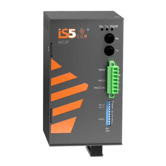
- Page 1 User Manual iSC2F Single Port RS-232/422/485 to Fiber Media Converter IEC61850-3 and IEEE1613 Compliant Version 2, Apr 2020 © 2020 iS5 Communications Inc. All rights reserved. UM-iSC2F-2-EN.docx...
- Page 2 User’s Manual COPYRIGHT NOTICE © 2020 iS5 Communications Inc. All rights reserved. No part of this publication may be reproduced in any form without the prior written consent of iS5 Communications Inc. (iS5). TRADEMARKS iS5Com is a registered trademark of iS5. All other trademarks belong to their respective owners.
-
Page 3: Table Of Contents
User’s Manual Table of Contents Getting Started .................. 1 Introduction ..........................1 Operating Modes ........................2 Configuring the Device ......................2 Serial-to-Fiber Conversion—Point-to-Point ................3 Fiber Repeater Mode ........................ 4 Serial Standard Conversion ...................... 5 Communication Ports ........................ 6 Fiber Optic Ports ........................ -
Page 4: Getting Started
IEC 61850-3 and IEEE 1613 standards. The iSC2F accepts a wide input voltage range from dual 9-36VDC or 36-75VDC power inputs to a single input of 110-370VDC or 90-264VAC, which makes it suitable for harsh operating environment. -
Page 5: Operating Modes
1.2 Operating Modes 1.3 Configuring the Device The ISC2F can be configured using the Mode DIP switch located on the right side off the enclosure. Use the DIP switch to change the operating mode of the ISC2F. The configuration settings are as follows:... -
Page 6: Serial-To-Fiber Conversion-Point-To-Point
User’s Manual Serial-to-Fiber Conversion—Point-to-Point 1. RS232 device 2. iSC2F 3. RS485 Device/ Network Note that the distance between the two ISC2F devices should be less than 5 km (3.1 mi). RS232 Device Position State Notes RS232 to fiber RS232-to-RS485/422 conversion... -
Page 7: Fiber Repeater Mode
57600 – 115200 Fiber Repeater Mode When a distance that is more than 5 km (3.1 mi) has to be supported, iSC2F must be used in Fiber Repeater mode. This mode supports extended distance between serial devices. 1. RS232 device 2. -
Page 8: Serial Standard Conversion
RS232 devices is connected to ground. In some instances (i.e. when connecting to large RS485 networks), it may be preferential for the user to leave the RS485/RS422 shield terminal unconnected to the ISC2F in this mode. UM-iSC2F-2-EN.docx Pages 5 of 12... -
Page 9: Communication Ports
User’s Manual 1.4 Communication Ports The iSC2F can be equipped with various types of communication ports to enhance its abilities and performance. To determine which ports are equipped on the device, refer to the factory data file available in specification. -
Page 10: Serial Terminal
User’s Manual Serial Terminal The ISC2F is equipped with a seven-terminal Phoenix-style connector. This connector can accommodate one RS232 connection, and one RS485/422 connection. The following is the pin- out for the serial terminal: Pin # Signal 1 (top) -
Page 11: Hardware Overview
User’s Manual HARDWARE OVERVIEW 2.1 Front Panel The ISC2F features various ports, controls and indicator LEDs on the front panel for configuring and troubleshooting the device. Number Description Function The power indicator LED illuminates when power Power Indicator LED is being supplied to the device. -
Page 12: Power Supply Connections
Equipment must be installed according to the applicable country wiring codes. Chassis Ground Connection The iSC2F chassis ground connection, located next to the terminal block, uses a #6-32 Screw. We recommend terminating the ground connection using a #6 ring lug, and a torque setting of 15 in.lbs (1.7Nm). -
Page 13: Hardware Installation
User’s Manual Hardware Installation The ISC2F is designed for maximum mounting and display flexibility. It can be equipped with connectors that allow it to be installed in a DIN rail. 3.1 DIN Rail Installation For DIN rail installations, the ISC2F can be equipped with a DIN rail bracket pre-installed on the back of the chassis. -
Page 14: Dimensions
User’s Manual 3.2 Dimensions All dimensions are shown in inches. UM-iSC2F-2-EN.docx Pages 11 of 12... -
Page 15: Specifications
User’s Manual SPECIFICATIONS Model Number iSC2F Physical Ports 10M Fiber port RS232/RS422/RS485 1 (2 for RS232 to RS485 conversion) Power Dual DC Inputs of 9-36VDC or Dual Input 36-75VDC, or single Input 110-370VDC or 90- Input power 264VAC Power consumption (Typ.)
Need help?
Do you have a question about the iSC2F and is the answer not in the manual?
Questions and answers