Table of Contents
Advertisement
Available languages
Available languages
Quick Links
Version 1.0
Published July 2018
Copyright©2018 ASRock INC. All rights reserved.
Copyright Notice:
No part of this documentation may be reproduced, transcribed, transmitted, or
translated in any language, in any form or by any means, except duplication of
documentation by the purchaser for backup purpose, without written consent of
ASRock Inc.
Products and corporate names appearing in this documentation may or may not
be registered trademarks or copyrights of their respective companies, and are used
only for identification or explanation and to the owners' benefit, without intent to
infringe.
Disclaimer:
Specifications and information contained in this documentation are furnished for
informational use only and subject to change without notice, and should not be
constructed as a commitment by ASRock. ASRock assumes no responsibility for
any errors or omissions that may appear in this documentation.
With respect to the contents of this documentation, ASRock does not provide
warranty of any kind, either expressed or implied, including but not limited to
the implied warranties or conditions of merchantability or fitness for a particular
purpose.
In no event shall ASRock, its directors, officers, employees, or agents be liable for
any indirect, special, incidental, or consequential damages (including damages for
loss of profits, loss of business, loss of data, interruption of business and the like),
even if ASRock has been advised of the possibility of such damages arising from any
defect or error in the documentation or product.
This device complies with Part 15 of the FCC Rules. Operation is subject to the following
two conditions:
(1) this device may not cause harmful interference, and
(2) this device must accept any interference received, including interference that
may cause undesired operation.
CALIFORNIA, USA ONLY
The Lithium battery adopted on this motherboard contains Perchlorate, a toxic substance
controlled in Perchlorate Best Management Practices (BMP) regulations passed by the
California Legislature. When you discard the Lithium battery in California, USA, please
follow the related regulations in advance.
"Perchlorate Material-special handling may apply, see www.dtsc.ca.gov/hazardouswaste/
perchlorate"
ASRock Website: http://www.asrock.com
Advertisement
Table of Contents

Subscribe to Our Youtube Channel
Related Manuals for ASROCK B250M DASH


Summary of Contents for ASROCK B250M DASH
- Page 1 (including damages for loss of profits, loss of business, loss of data, interruption of business and the like), even if ASRock has been advised of the possibility of such damages arising from any defect or error in the documentation or product.
- Page 2 If you require assistance please call ASRock Tel : +886-2-28965588 ext.123 (Standard International call charges apply) The terms HDMI™...
-
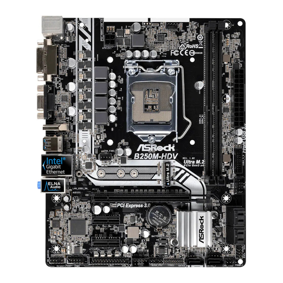
Page 3: Motherboard Layout
B250M DASH Motherboard Layout CHA_FAN1 CPU_FAN1 CPU_FAN2 ATX12V1 USB 3.1 Gen1 T: USB3_TA_1 B: USB3_TC_1 USB 3.1 Gen1 T: USB3 B: USB4 USB 2.0 Top: T: USB1 RJ-45 B: USB2 Ultra M.2 PCIe Gen3 x4 CHA_FAN2 PCI Express 3.0 PCIE1... - Page 4 No. Description ATX 12V Power Connector (ATX12V1) Chassis Fan Connector (CHA_FAN1) CPU Fan Connector (CPU_FAN1) CPU Fan Connector (CPU_FAN2) 2 x 288-pin DDR4 DIMM Slots (DDR4_A1, DDR4_B1) 2 x 288-pin DDR4 DIMM Slots (DDR4_A2, DDR4_B2) ATX Power Connector (ATXPWR1) USB 3.1 Gen1 Header (USB3_5_6) SATA3 Connector (SATA3_0) SATA3 Connector (SATA3_1) Chassis Fan Connector (CHA_FAN2)
- Page 5 B250M DASH I/O Panel No. Description No. Description PS/2 Mouse Port USB 3.1 Gen1 Ports (USB3_3_4) D-Sub Port USB 3.1 Gen1 Type-A Port (USB3_TA_1) LAN RJ-45 Port* USB 3.1 Gen1 Type-C Port (USB3_TC_1) Line In (Light Blue)** DisplayPort 1.2 Front Speaker (Lime)**...
- Page 6 ** To configure 7.1 CH HD Audio, it is required to use an HD front panel audio module and enable the multi- channel audio feature through the audio driver. Please set Speaker Configuration to “7.1 Speaker”in the Realtek HD Audio Manager. Function of the Audio Ports in 7.1-channel Configuration: Port Function...
-
Page 7: Chapter 1 Introduction
ASRock’s website without further notice. If you require technical support related to this motherboard, please visit our website for specific information about the model you are using. You may find the latest VGA cards and CPU support list on ASRock’s website as well. ASRock website http://www.asrock.com. -
Page 8: Specifications
1.2 Specifications Platform • Micro ATX Form Factor • Solid Capacitor design • Supports 7 and 6 Generation Intel® Core i7/i5/i3/ Pentium®/Celeron® Processors (Socket 1151) • Digi Power design • 6 Power Phase design • Supports Intel® Turbo Boost 2.0 Technology Chipset • Intel®... - Page 9 * To configure 7.1 CH HD Audio, it is required to use an HD front panel audio module and enable the multi-channel audio feature through the audio driver. • Premium Blu-ray Audio support • Supports Surge Protection (ASRock Full Spike Protection) • ELNA Audio Caps...
- Page 10 2230/2242/2260/2280 M.2 PCI Express module up to Gen3 x2 (16 Gb/s)** ** If PCIE2 slot or PCI slot is occupied, the PCIe-type M.2 device on M2_1 socket will run at Gen3 x2 (16 Gb/s). ** Supports NVMe SSD as boot disks ** Supports ASRock U.2 Kit...
- Page 11 B250M DASH Connector • 1 x Buzzer • 1 x Onboard TPM 2.0 • 1 x Print Port Header • 2 x COM Port Headers • 1 x Chassis Intrusion and Speaker Header • 2 x CPU Fan Connectors (1 x 4-pin, 1 x 3-pin) * The CPU Fan Connector supports the CPU fan of maximum 1A (12W) fan power.
- Page 12 * To install Windows® 7 OS, a modified installation disk with xHCI drivers packed into the ISO file is required. Please refer to page 39 for more detailed instructions. * For the updated Windows® 10 driver, please visit ASRock’s website for details: http://www.asrock.com Certifica- • FCC, CE...
-
Page 13: Chapter 2 Installation
B250M DASH Chapter 2 Installation This is a Micro ATX form factor motherboard. Before you install the motherboard, study the configuration of your chassis to ensure that the motherboard fits into it. Pre-installation Precautions Take note of the following precautions before you install motherboard components or change any motherboard settings. -
Page 14: Installing The Cpu
2.1 Installing the CPU 1. Before you insert the 1151-Pin CPU into the socket, please check if the PnP cap is on the socket, if the CPU surface is unclean, or if there are any bent pins in the socket. Do not force to insert the CPU into the socket if above situation is found. Otherwise, the CPU will be seriously damaged. - Page 15 B250M DASH...
- Page 16 Please save and replace the cover if the processor is removed. The cover must be placed if you wish to return the motherboard for after service.
-
Page 17: Installing The Cpu Fan And Heatsink
B250M DASH 2.2 Installing the CPU Fan and Heatsink... -
Page 18: Installing Memory Modules (Dimm)
2.3 Installing Memory Modules (DIMM) This motherboard provides four 288-pin DDR4 (Double Data Rate 4) DIMM slots, and supports Dual Channel Memory Technology. 1. For dual channel configuration, you always need to install identical (the same brand, speed, size and chip-type) DDR4 DIMM pairs. 2. - Page 19 B250M DASH...
-
Page 20: Expansion Slots (Pci And Pci Express Slots)
2.4 Expansion Slots (PCI and PCI Express Slots) There is 1 PCI slot and 3 PCI Express slots on the motherboard. Before installing an expansion card, please make sure that the power supply is switched off or the power cord is unplugged. Please read the documentation of the expansion card and make necessary hardware settings for the card before you start the installation. -
Page 21: Jumpers Setup
B250M DASH 2.5 Jumpers Setup The illustration shows how jumpers are setup. When the jumper cap is placed on the pins, the jumper is “Short”. If no jumper cap is placed on the pins, the jumper is “Open”. The illustration shows a 3-pin jumper whose pin1 and pin2 are “Short”... -
Page 22: Onboard Headers And Connectors
2.6 Onboard Headers and Connectors Onboard headers and connectors are NOT jumpers. Do NOT place jumper caps over these headers and connectors. Placing jumper caps over the headers and connectors will cause permanent damage to the motherboard. System Panel Header Connect the power PLED+ PLED-... - Page 23 B250M DASH Chassis Intrusion and Please connect the SPEAKER DUMMY Speaker Header chassis intrusion and the DUMMY (7-pin SPK_CI1) chassis speaker to this (see p.1, No. 17) header. SIGNAL DUMMY Serial ATA3 Connectors These six SATA3 (SATA3_0: connectors support SATA see p.1, No.
- Page 24 Front Panel Audio Header This header is for PRESENCE# (9-pin HD_AUDIO1) MIC_RET connecting audio devices OUT_RET (see p.1, No. 25) to the front audio panel. OUT2_L J_SENSE OUT2_R MIC2_R MIC2_L 1. High Definition Audio supports Jack Sensing, but the panel wire on the chassis must support HDA to function correctly.
- Page 25 B250M DASH ATX Power Connector This motherboard pro- (24-pin ATXPWR1) vides a 24-pin ATX power (see p.1, No. 7) connector. To use a 20-pin ATX power supply, please plug it along Pin 1 and Pin ATX 12V Power This motherboard pro-...
- Page 26 2.7 M.2_SSD (NGFF) Module Installation Guide The M.2, also known as the Next Generation Form Factor (NGFF), is a small size and versatile card edge connector that aims to replace mPCIe and mSATA. The Ultra M.2 Socket (M2_1) supports type 2230/2242/2260/2280 M.2 SATA3 6.0 Gb/s module and M.2 PCI Express module up to Gen3 x4 (32 Gb/s).
- Page 27 B250M DASH Step 3 Move the standoff based on the module type and length. The standoff is placed at the nut location D by default. Skip Step 3 and 4 and go straight to Step 5 if you are going to use the default nut.
- Page 28 SATA3 2260 TS512GMTS600 Transcend 512GB SATA3 2280 TS512GMTS800 V-Color 120GB SATA3 2280 VLM100-120G-2280B-RD V-Color 240GB SATA3 2280 VLM100-240G-2280B-RD V-Color 240GB SATA3 2280 VSM100-240G-2280 For the latest updates of M.2_SSD (NFGG) module support list, please visit our website for details: http://www.asrock.com...
- Page 29 B250M DASH M.2_SSD (NGFF) Module Support List (M2_2) Vendor Size Interface Length Plextor 256GB PCIe 2280 PX-G256M6e Plextor 512GB PCIe 2280 PX-G512M6e SanDisk 128GB PCIe 2260 SD6PP4M-128G SanDisk 256GB PCIe 2260 SD6PP4M-256G For the latest updates of M.2_SSD (NFGG) module support list, please visit our website...
-
Page 30: Contenido Del Paquete
Podrá encontrar las últimas tarjetas VGA, así como la lista de compatibilidad de la CPU, en el sitio web de ASRock. Sitio web de ASRock http://www.asrock.com. -
Page 31: Especificaciones
B250M DASH 1.2 Especificaciones Plataforma • Factor de forma Micro ATX • Diseño de condensador sólido • Admite la familia de procesadores Intel® Core i7/i5/i3/Pentium®/ ª ª Celeron® (zócalo 1151) de la 7 generación • Digi Power design • Diseño de 6 fases de alimentación • Admite la tecnología Intel®... - Page 32 * Para configurar 7.1 Audio CH HD, deberá utilizar un módulo del panel frontal de audio HD y habilitar la característica de audio multicanal a través del controlador de audio. • Compatible con audio Blu-ray Premium • Compatible con protección por sobretensión (protección ASRock Full Spike) • Tapas de audio ELNA...
- Page 33 ** Si la ranura PCIE2 o la ranura PCI está ocupada, el dispositivo M.2 de tipo PCIe en el zócalo M2_1 funcionará a Gen3 x2 (16 Gb/s). ** Admite unidad de estado sólido de NVMe como disco de arranque ** Admite el kit U.2 de ASRock...
- Page 34 Conector • 1 x Zumbador • 1 x TPM 2.0 • 1 x Base de conexiones de puerto de impresión • 2 x Base de conexiones de puerto COM • 1 x Cabezal de intrusión de chasis y de altavoces • 2 x Conectores para ventilador de la CPU (1 x 4 contactos, 1 x 3 contactos) * El conector para ventilador de la CPU admite ventilador de la CPU...
- Page 35 ErP/EuP) * Para obtener información detallada del producto, visite nuestro sitio Web: http://www.asrock.com Tenga en cuenta que hay un cierto riesgo implícito en las operaciones de aumento de la velocidad del reloj, incluido el ajuste del BIOS, aplicando la tecnología de aumento de velocidad liberada o utilizando las herramientas de aumento de velocidad de otros fab- ricantes.
- Page 36 1.3 Instalación de los puentes La instalación muestra cómo deben instalarse los puentes. Cuando la tapa de puente se coloca en los contactos, el puente queda “Corto”. Si no coloca la tapa de puente en los contactos, el puente queda “Abierto”. La ilustración muestra un puente de 3 contactos cuyo contacto 1 y contacto 2 son “Cortos”...
- Page 37 B250M DASH 1.4 Conectores y cabezales incorporados Los cabezales y conectores incorporados NO son puentes. NO coloque tapas de puente so- bre estos cabezales y conectores. Si coloca tapas de puente sobre los cabezales y conectores dañará de forma permanente la placa base.
- Page 38 Cabezal de intrusión de Conecte la intrusión de SPEAKER DUMMY chasis y de altavoces chasis y el altavoz del DUMMY (SPK_CI1 de 7 pines) chasis a este cabezal. (consulte la pág.1, nº 17) SIGNAL DUMMY Conectores Serie ATA3 Estos seis conectores (SATA3_0: SATA3 son compatibles consulte la pág.1, n.º...
- Page 39 B250M DASH Cabezal de audio del panel Este cabezal se utiliza para PRESENCE# frontal MIC_RET conectar dispositivos de OUT_RET (HD_AUDIO1 de 9 pines) audio al panel de audio (consulte la pág.1, nº 25) frontal. OUT2_L J_SENSE OUT2_R MIC2_R MIC2_L 1. El Audio de Alta Definición (HDA, en inglés) es compatible con el método de sensor de conectores, sin embargo, el cable del panel del chasis deberá...
- Page 40 Conector de alimentación Esta placa base contiene un conector de aliment- (ATXPWR1 de 24 pines) ación ATX de 24 pines. (consulte la pág.1, nº 7) Para utilizar una toma de alimentación ATX de 20 pines, conéctela en los Pines del 1 al 13. Conector de alimentación Esta placa base contiene ATX de 12V...
-
Page 41: Enabling Usb Ports For Windows® 7 Installation
Requirements A Windows® 7 installation disk or USB drive • A Windows® PC • Win7 USB Patcher (included in the ASRock Support CD or downloaded from • website) Scenarios You have an ODD and PS/2 ports: If there is an optical disc drive, PS/2 ports and PS/2 Keyboard or mouse on your computer, you can skip the instructions below and go ahead to install Windows®... - Page 42 Instructions Step 1 Insert the Windows® 7 installation disk or USB drive to your system. Step 2 Extract the tool (Win7 USB Patcher) and launch it. Step 3 Select how you want to install Windows 7 later. Step 4 Locate your Win7 source folder or your ISO file.
- Page 43 B250M DASH Step 5 Select the USB storage, compact disk or destination folder for the new Windows 7 installation file. Step 6 Click “Start” to begin. Step 7 Now you are able to install Windows® 7 on Intel® new processors with the new burned CD.
-
Page 46: Contact Information
Contact Information If you need to contact ASRock or want to know more about ASRock, you’re welcome to visit ASRock’s website at http://www.asrock.com; or you may contact your dealer for further information. For technical questions, please submit a support request form at https://event.asrock.com/tsd.asp... -
Page 47: Declaration Of Conformity
13848 Magnolia Ave, Chino, CA91710 Phone/Fax No: +1-909-590-8308/+1-909-590-1026 hereby declares that the product Product Name : Motherboard B250M DASH Model Number : Conforms to the following speci cations: FCC Part 15, Subpart B, Unintentional Radiators Supplementary Information: is device complies with part 15 of the FCC Rules. Operation is subject to the... -
Page 48: Eu Declaration Of Conformity
EU Declaration of Conformity For the following equipment: Motherboard (Product Name) B250M DASH / ASRock (Model Designation / Trade Name) ASRock Incorporation (Manufacturer Name) 2F., No.37, Sec. 2, Jhongyang S. Rd., Beitou District, Taipei City 112, Taiwan (R.O.C.) (Manufacturer Address) EMC —Directive 2014/30/EU (from April 20th, 2016)
Need help?
Do you have a question about the B250M DASH and is the answer not in the manual?
Questions and answers