Table of Contents
Advertisement
Quick Links
Advertisement
Table of Contents

Related Manuals for Magpowr Maxcess DLCA NET-ECAT

Summary of Contents for Magpowr Maxcess DLCA NET-ECAT
- Page 1 MAGPOWR TENSION CONTROL DLCA NET-ECAT User Manual MI 850A365 1...
-
Page 2: Table Of Contents
CONTENTS INTRODUCTION About these operating instructions ..............5 Product overview ..................... 6 1.2.1 Additional tools ................... 7 Model number ....................8 Serial number....................8 SAFETY Instructions for use ..................9 INSTALLATION Mechanical ....................12 Electrical ....................... 13 Wiring diagrams .................... 13 Analog output and digital input connections .......... - Page 3 CONTENTS Alarm ......................48 Command interface..................48 8.6.1 Command request ................49 8.6.2 Command response ................53 Function information ..................54 8.7.1 Security ..................... 54 8.7.2 Reset non-volatile (NV) memory to defaults ........55 8.7.3 Zeroing the tension ................55 8.7.4 Calibrate the analog outputs (not normally used) ......
- Page 4 CONTENTS FIGURES Figure 1. DLCA NET dimensions ..................12 Figure 2. DLCA NET1 wiring using MAGPOWR load cells ............. 14 Figure 3. DLCA NET2 wiring using MAGPOWR load cells ............. 15 Figure 4. Non-MAGPOWR load cell wiring ................16 Figure 5. DLCA NET-ECAT common wiring ................. 18 Figure 6.
-
Page 5: Introduction
INTRODUCTION 1.0 Introduction About these operating instructions All of the information herein is the exclusive proprietary property of Maxcess International, and is disclosed with the understanding that it will be retained in confidence and will neither be duplicated nor copied in whole or in part nor be used for any purpose other than for which disclosed. -
Page 6: Product Overview
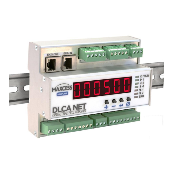
INTRODUCTION Product overview The DLCA NET-ECAT is a DIN rail-mounted digital load cell amplifier that provides excitation voltage for load cells, measures the returned force signal, and then converts this signal into a digital value that represents tension and analog output signals. -
Page 7: Additional Tools
INTRODUCTION Product overview continued The DLCA NET-ECAT has three alarm outputs. Two of the alarm outputs can be configured to sense tension limits on either of the two sensor inputs, or the total tension for the one tension zone amplifier. The third alarm output is on when there are no load cell wiring problems detected or power faults. -
Page 8: Model Number
INTRODUCTION Model number The model number and the serial number are shown on the enclosure. The model number consists of the base model DLCA NET followed by the numeral 1 or 2 to denote number of tension zones the product will read, followed by "ECAT". Available models DLCA NET1-ECAT –... -
Page 9: Safety
SAFETY INSTRUCTIONS 2.0 Safety Instructions for use To ensure safe and problem free installation of the digital load cell amplifier, the digital load cell amplifier must be properly transported and stored, professionally installed and placed in operation. Proper operation and maintenance will ensure a long service life of the device. - Page 10 SAFETY INSTRUCTIONS Basic safety information Proper use The DLCA NET-ECAT load cell amplifier is intended to be used on machines or systems to amplify the signal from MAGPOWR or competitor load cells. For indoor operation, see environmental specifications on page 69.
- Page 11 SAFETY INSTRUCTIONS Basic safety information continued WARNING – Death or injury can result from unexpected movement of the machine into which the DLCA NET-ECAT is installed. Protect against unexpected movement by removing electrical power from the digital load cell amplifier and the machine into which the digital load cell amplifier is being installed.
-
Page 12: Installation
INSTALLATION 3.0 Installation Use shielded cable for all cables except for power cable. Mechanical 1. Mount the DLCA NET to a 35 mm DIN rail. See Figure 1 for DLCA NET dimensions. Figure 1. DLCA NET dimensions www.maxcessintl.com DLCA NET-ECAT MI 850A365 1 Page 12 of 72... -
Page 13: Electrical
4. Connect the Ethernet ports into a fieldbus network or computer. 5. Connect analog outputs, if desired. Wiring diagrams Figures 2 and 3: DLCA NET wiring connections using MAGPOWR load cells Figure 4: Connecting non-MAGPOWR load cells TB2 is Channel 1 or Tension Zone 1 input. -
Page 14: Figure 2. Dlca Net1 Wiring Using Magpowr Load Cells
DLCA NET1 one or two load cells from one tension zone Figure 2. DLCA NET1 wiring using MAGPOWR load cells www.maxcessintl.com DLCA NET-ECAT MI 850A365 1 Page 14 of 72... -
Page 15: Figure 3. Dlca Net2 Wiring Using Magpowr Load Cells
DLCA NET2 two tension zones, one or two load cells from each zone Figure 3. DLCA NET2 wiring using MAGPOWR load cells www.maxcessintl.com DLCA NET-ECAT MI 850A365 1 Page 15 of 72... -
Page 16: Figure 4. Non-Magpowr Load Cell Wiring
Two Half Bridge One Half Bridge 500 mV Load Cells 500 mV Load Cells Precision bridge completion resistors; contact load cell manufacturer for values. Figure 4. Non-MAGPOWR load cell wiring www.maxcessintl.com DLCA NET-ECAT MI 850A365 1 Page 16 of 72... -
Page 17: Analog Output And Digital Input Connections
INSTALLATION Analog output and digital input connections DLCA NET1-ECAT: One tension zone amplifier Output 1 is channel 1. (TB7.1, TB7.2, and TB7.3) Output 2 is channel 2. (TB7.4, TB7.5, and TB7.6) Output 3 is the sum of channel 1 and channel 2. (TB7.7, TB7.8, and TB7.6) The meter output is the sum tension signal. -
Page 18: Figure 5. Dlca Net-Ecat Common Wiring
INSTALLATION Figure 5. DLCA NET-ECAT common wiring www.maxcessintl.com DLCA NET-ECAT MI 850A365 1 Page 18 of 72... -
Page 19: Figure 6. Dlca Net1-Ecat One Tension Zone Analog Outputs Wiring
INSTALLATION Figure 6. DLCA NET1-ECAT one tension zone analog outputs wiring Figure 7. DLCA NET2-ECAT two tension zone analog outputs wiring www.maxcessintl.com DLCA NET-ECAT MI 850A365 1 Page 19 of 72... -
Page 20: Figure 8. Magpowr And Non-Magpowr Load Cell Wiring
INSTALLATION Figure 8. MAGPOWR and non-MAGPOWR load cell wiring www.maxcessintl.com DLCA NET-ECAT MI 850A365 1 Page 20 of 72... -
Page 21: Operation
OPERATION 4.0 Operation There are four control buttons on the DLCA NET. [+] = increment [-] = decrement [ ] = enter or save function* [n] = zero the displayed tension (the zero button) ]. * For clarity, these instructions use the word [ENTER] instead of the symbol [ Power On The DLCA NET-ECAT will display the software version number when power is first applied for five seconds and then the DLCA... -
Page 22: Table 1. Load Cell Diagnostic Errors
OPERATION Er 12 Sensor 1 Failure or other wiring error. Sensor 2 White (S+) or Black (S-) wire Example: Green and White wire are disconnected. swapped, etc. Er 16 Good Sensor 2 Red (P+) wire disconnected. Er 17 Sensor 1 White (S+) or Black (S-) wire Sensor 2 Red (P+) wire disconnected. -
Page 23: Zeroing Tension Display
OPERATION Zeroing tension display While displaying tension, press the [] button for two seconds to zero the tension in the tension zone being displayed. The outputs will also be zeroed. Connecting the digital input 1 or 2 (zero) to either +5V or +24V for greater than 500 ms will zero the displayed tension and output for the respective tension zone. -
Page 24: Led Indicators
OPERATION LED indicators EtherCAT RUN Channel 1 (Tension Zone 1) Channel 2 (Tension Zone 2) Tension Sum Alarm 1 Alarm 2 EtherCAT ERROR Power good and fault LED EtherCAT link / activity LED Figure 9. LED indicators Power Good (Yellow) The Power Good status indicator shows power good or a fault. -
Page 25: Which Sensor Inputs Used
Load cell excitation voltage The load cell excitation voltage can be either 5V or 7.5V. MAGPOWR load cells use 7.5V. 5V or 7.5V can be used for competitors’ non-MAGPOWR load cells. Use parameter P.03 to select voltage before performing any tension calibrations. -
Page 26: Programming Mode
OPERATION Programming mode Enter the programming menu Press and hold [+] and [-] for two seconds. Exit the programming menu Press and hold [+] and [-] for two seconds from a menu item other than the load cell calibrations menu items. Also: while showing parameter P.17, you may press [Enter] to exit the menu and return to displaying the tension. -
Page 27: Calibrate Tension Using Menu
Press [Enter] to see the present load cell excitation voltage. Select 7.5V if using MAGPOWR load cells. Select either 5V or 7.5V if using non-MAGPOWR load cells Press and hold [Enter] for two seconds (until the display starts flashing) to store the changes. - Page 28 CALIBRATE TENSION USING MENU Precision calibration continued Use [+] and/or [-] to go to CAL1.1 or CAL2.1. Press [Enter] to enter the sub-menu. Display now shows C11.1 or C21.1. Unload the load cells roller and press [Enter]. The DLCA NET-ECAT will now zero out the idler roll weight and show a wait display.
-
Page 29: Figure 10. Apply Calibration Tension
CALIBRATE TENSION USING MENU Precision calibration continued Display now shows C11.5 or C21.5. Apply the calibration load to the load cell roller using a temporary web or rope and a known weight entered in C11.4 or C21.4. The temporary web should follow the normal web path. -
Page 30: Weightless Calibration
000.000, 00.0000, 0.00000}. Display now shows C12.3 or C22.3. Press [Enter] and enter the load cell sensitivity in 0.1 mV/V units. MAGPOWR load cells have a sensitivity of 2.1 mV/V. (Consult the manual of competitor’s load cell if using non-MAGPOWR load cells.) Press and hold [Enter] for two seconds (until the display starts flashing) to store the parameter. -
Page 31: Figure 11. Weightless Calibration Angles
CALIBRATE TENSION USING MENU Weightless calibration continued Display now shows C12.4 or C22.4. Press [Enter] and enter the combined load cell rating. Press and hold [Enter] for two seconds (until the display starts flashing) to store the parameter. Range {0, 999000}. Display now shows C12.5 or C22.5. -
Page 32: Table 2. Calibration Errors
CALIBRATE TENSION USING MENU Weightless calibration continued Display now shows C12.8 or C22.8. Press [Enter] to start the weightless calibration. The display will show a wait screen, and then display PASS for a successful calibration or an error code to indicate an issue with the calibration. -
Page 33: Entering Maximum Tension
ENTERING MAXIMUM TENSION 6.0 Entering maximum tension The following are examples of displaying tension that results from the value entered for maximum tension and the selection of the decimal point position. The DLCA NET-ECAT displays tension with three significant digits. Example 1 Using two GTSD-15000M load cells: ... - Page 34 ENTERING MAXIMUM TENSION Entering maximum tension continued Example 2 Using two GTSB-2200 load cells: The rated load is 4400 lbs. The application’s maximum tension is 2000 lbs. Enter decimal point position as 00.00. Enter Maximum tension as 2.00. ...
-
Page 35: Parameters
PARAMETERS 7.0 Parameters This section describes the parameters available in the DLCA NET-ECAT. Filtering The tension display and the analog outputs have a separate low pass filter. The communication tension values can use either the tension display filter or have no filtering. The tension display filter response can be set from 500 Hz to 0.01 Hz. -
Page 36: Alarm Setup And Operation
PARAMETERS Alarm setup and operation The following parameters describe the setup and operation of the alarms. Parameter Description Units Default Range AL1.1 Tension Channel/Zone used for alarm DLCA NET 1-ECAT AL2.1 DLCA NET 1-ECAT {0, 2} 0 = Channel 1 1 = Channel 2 DLCA NET 2-ECAT 2 = Tension Sum... -
Page 37: Alarm Operation With Hysteresis
PARAMETERS 7.2.1 Alarm operation with hysteresis Alarm activation type 0 Alarm turns on when tension is greater than High value. Alarm turns off when tension is less than (HighValue – (HysteresisPercent * Maximum Tension)) Alarm activation type 1 Alarm turns on when tension is less than Low value. Alarm turns off when tension is greater than (LowValue + (HysteresisPercent * MaximumTension)) Alarm activation type 2... -
Page 38: Hardware Configuration Parameters
PARAMETERS Hardware configuration parameters These parameters configure the hardware or provide information about the hardware. Parameter Description Default P.01 Zero Tension Lock Issuing a Zero Tension Zone 1 or Zone 2 command will immediately zero the tension value. It does not do a zero calibration, but does record the current offset signal and stores it for subtraction from the reading. - Page 39 PARAMETERS Product Type (only available on communications and web server) Set by (Communication parameter 0x204) factory 1 = DLCA NET1 2 = DLCA NET2 3 = DLCA NET-SLIM1 4 = DLCA NET-SLIM2 5 = DLCA NET-IP651 6 = DLCA NET-IP652 www.maxcessintl.com DLCA NET-ECAT MI 850A365 1...
-
Page 40: Miscellaneous Parameters
PARAMETERS Miscellaneous parameters Parameter Description Default P.05 Decimal Point Position, Tension Zone 1 Set the decimal point position to show when displaying tension. 0 = 000000 1 = 000000. 2 = 00000.0 3 = 0000.00 4 = 000.000 5 = 00.0000 6 = 0.00000 P.06 Tension Polarity, Tension Zone 1... -
Page 41: Analog Output Scaling
PARAMETERS Analog output scaling Each analog output’s output values for zero tension and maximum tension can be set by the following parameters. The default for the 0 to 20mA outputs is 0 and 20mA. Use these parameters to scale the 0 to 20mA output to be 4 to 20mA. Parameter Description Units... -
Page 42: Calibrate The Analog Outputs (Not Normally Changed)
PARAMETERS OP4.2 Sets the 0 to 1mA meter output 1 0.01 mA 01.00 {00.00, current when the tension is equal to 01.00} maximum tension. OP4.3 Sets the 0 to 1 meter output 2 0.01 mA 00.00 {00.00, current when the tension is zero. 01.00} OP4.4 Sets the 0 to 1mA meter output 2... - Page 43 PARAMETERS CO.33 Sets the 0 to 20mA output to 0%. {0, 9999} Change the value until the meter reads 0.00 mA. CO.34 Sets the 0 to 20mA output to 100%. {0, 9999} Change the value until the meter reads 20.00 mA, Meter Output CO.41 Sets the meter output 1 to 0%.
-
Page 44: Password
PARAMETERS Password Parameter Description Range P.00 Password {0, 9999} When the DLCA NET-ECAT is locked, all parameters will be viewable but cannot be changed and no calibrations can be performed. To lock or unlock the DLCA NET-ECAT press [Enter] to show the lock and unlock status, displayed as ULOC for unlocked and LOC for locked. -
Page 45: Communications Interface
COMMUNICATIONS INTERFACE 8.0 Communications interface Electronic datasheets are available for EtherCAT. Cyclic parameters The cyclic parameters are available to read tension and status from the DLCA NET-ECAT and to send commands and parameters to the DLCA NET-ECAT. RO = Read only WO = Write only uint16 = unsigned 16-bit integer int32 = signed 32-bit integer... -
Page 46: Actual Tension Data
COMMUNICATIONS INTERFACE Actual tension data Tension is read from the DLCA NET-ECAT in the four cyclic parameters Tension 1, Tension 2, Tension Sum, and Tension Difference. The tension value is a 32-bit signed integer and is scaled to be 160 times the Maximum Tension value ignoring the decimal point position set by parameter 0x207 or 0x217. -
Page 47: Security State
COMMUNICATIONS INTERFACE Security state The status of security is shown in the Security State cyclic parameter. Value Status System is unlocked and changes can be made. System is locked and changes cannot be made. Status The Status cyclic parameter shows power good, power failure errors, and load cell check errors. -
Page 48: Alarm
COMMUNICATIONS INTERFACE Alarm The Alarm cyclic parameter shows the Alarm 1 and Alarm 2 state. Bit 0 is the status of alarm 1. Bit 1 is the status of alarm 2. Bit = 0, Alarm OFF Bit = 1, Alarm ON Command interface Command Request Commands are entered into the... -
Page 49: Command Request
COMMUNICATIONS INTERFACE 8.6.1 Command request Commands start at 0x0 and continue to 0x1FF. Parameters start at 0x200 and continue to 0x3FF. For parameters, add 0x1000 for a Write and 0x0000 for a Read to the parameter number. Command Read or write Command/parameter list WO = Write Only, RO = Read only, RW = Read and Write The parameter Class specifies which group this parameter... - Page 50 COMMUNICATIONS INTERFACE 0x00F Cal Output 2, 10V, 0% Function None WO – int16 See 8.7.4 0x010 Cal Output 2, 10V, 100% Function None WO – int16 See 8.7.4 0x011 Cal Output 2, 20mA, 0% Function None WO – int16 See 8.7.4 0x012 Cal Output 2, 20mA, 100% Function...
- Page 51 COMMUNICATIONS INTERFACE 0x216 Tension Polarity Parameter LC Cal RW – int16 Configuration Tension 2 (Tension Zone 2) 0x217 DP Position Parameter Parm RW – int16 See 7.4 0x218 ADC PGA Gain Parameter LC Cal RW – int16 0x219 Tension Zero Offset Parameter LC Cal RW –...
- Page 52 COMMUNICATIONS INTERFACE Output 2 0x23B 0 to 10V Zero Offset Parameter Out Cal RW – int16 See 8.7.4 0x23C 0 to 10V Gain Parameter Out Cal RW – int16 See 8.7.4 0x23D 0 to 10V Zero Offset User Parameter Parm RW –...
-
Page 53: Command Response
COMMUNICATIONS INTERFACE 8.6.2 Command response Command Response A command response will be returned in the register. The response consists of a message type, an error or message number and the request command code all OR’ed together. When reading a parameter the value of the parameter will be returned Command Response Parameter Command in the... -
Page 54: Function Information
COMMUNICATIONS INTERFACE Function information This section describes how the functions are used. 8.7.1 Security The DLCA NET-ECAT can be locked out to prevent parameter changes and calibrations from being performed. Setting or clearing security To set or clear the security state, two identical passwords must be entered using the command Password 1 Entry and Password 2 Entry. -
Page 55: Reset Non-Volatile (Nv) Memory To Defaults
COMMUNICATIONS INTERFACE 8.7.2 Reset non-volatile (NV) memory to defaults These commands will reset the specified parameters to factory defaults. Command Function Explanation Reset parameters belonging to Reset NV Parameters 0x019 Only the Parameter class. Reset parameters belonging to Reset NV Load Cell 0x01A Calibrations Only the Load Cell Calibration class. - Page 56 COMMUNICATIONS INTERFACE Command Description Range Output 1 0x007 Sets the 0 to 10V output to 0%. {0, 9999} Change the value until the meter reads 0.00 volts. 0x008 Sets the 0 to 10V output to 100% {0, 9999} Change the value until the meter reads 10.00 volts. 0x009 Sets the 0 to 20mA output to 0%.
-
Page 57: Get Or Set Parameters
COMMUNICATIONS INTERFACE Get or set parameters 8.8.1 Get a parameter To get the value of a parameter, enter the parameter number in Command Request. The Command Response Parameter returned will contain the value of the parameter. 8.8.2 Set a parameter To set the value of a parameter, enter the value of the parameter Command Request Parameter. - Page 58 COMMUNICATIONS INTERFACE 0x241 Sets the 0 to 20mA output current 0.01 mA 0400 {0000, when the tension is zero. 2000} 0x242 Sets the 0 to 20mA output current 0.01 mA 2000 {0000, when the tension is equal to 2000} maximum tension. Output 3 0x246 Sets the 0 to 10V output voltage when...
-
Page 59: Calibrate Tension Through The Fieldbus Procedure
CALIBRATE TENSION THROUGH FIELDBUS 9.0 Calibrate tension through the fieldbus procedure The DLCA NET-ECAT has two modes of calibration: Precision and Weightless. Precision calibration is used when applying a known weight with a rope in the web path to the load cells for calibration. -
Page 60: Figure 12. Apply Calibration Tension
CALIBRATE TENSION THROUGH FIELDBUS Precision calibration procedure continued When performing a calibration, both the zero and precision calibrate steps must be done in sequence before a calibration is valid. If only zeroing the tension is required, use the 0x1E or 0x1F command. - Page 61 CALIBRATE TENSION THROUGH FIELDBUS Precision calibration procedure continued Tension Polarity If the calibration is successful, then (0x216 or 0x223) will automatically be set to show positive tension when force is applied in the direction of the calibration force. The following parameters in the group Configuration Tension 1 Configuration Tension 2 are set by the calibration...
-
Page 62: Weightless Calibrate Tension Procedure
Load Cell Sensitivity (units 0.1 mV/V) {0, 1000} 0x222 Enter the load cell sensitivity in mV/V. MAGPOWR load cells have a sensitivity of 2.1 mV/V. To enter 2.1 enter value of 21. Set the Load Cell excitation voltage 0x201 and which sensor inputs are used 0x203. - Page 63 CALIBRATE TENSION THROUGH FIELDBUS Weightless calibration procedure continued When performing a calibration, both the zero and WEIGHTLESS calibrate steps must be done in sequence before a calibration is valid. If only zeroing the tension is required, use the 0x1E or 0x1F command.
-
Page 64: Figure 13. Weightless Calibration Angles
CALIBRATE TENSION THROUGH FIELDBUS Weightless calibration procedure continued Configuration Tension 1 The following parameters in the group Configuration Tension 2 are set by the calibration procedure. Parameter Name Default Range 0x208 or 0x218 ADC PGA Gain 1 {0, 7} 0x209 or 0x219 Display Tension 1A Zero Offset {-0xFFFFFF, 0xFFFFFF} Display Tension 1B Zero Offset... -
Page 65: Calibration Errors Returned
CALIBRATE TENSION THROUGH FIELDBUS Calibration errors returned Value Error description and solution 0x00 Calibration was successful. No Errors found. Signal read by the amplifier is too large when maximum tension is applied. 0x01 This is caused by maximum tension being too large. Reduce maximum tension. -
Page 66: Web Server
WEB SERVER 10.0 Web server Access the web server in the DLCA NET-ECAT An Ethernet connection must be made to Ethernet Port 2 only. The DLCA NET-ECAT must be disconnected from the EtherCAT network and then power must be cycled. The DLCA NET-ECAT will allow non-EtherCAT traffic on Ethernet Port 2 after restarting as long as no EtherCAT traffic is detected on either Ethernet port. -
Page 67: Tension Calibration From Web
WEB SERVER 10.1 Tension calibration from web pages To calibrate tension from the web pages, edit the parameters below in the proper tension zone before performing the calibration commands. 10.1.1 Precision calibration from web pages For Precision Calibrate enter these parameters: Load Cell Excitation voltage (on Hardware web page) Which Sensor Inputs Used (on Hardware web page) Maximum Tension... -
Page 68: Zero Tension From Web
WEB SERVER 10.2 Zero tension from web pages To zero the tension in a tension zone: 1. Unload the load cells. 2. Click on the link "Zero Tension Zone x". This is the same as pressing the [] button on the front panel. www.maxcessintl.com DLCA NET-ECAT MI 850A365 1... - Page 69 SPECIFICATIONS 11.0 Specifications General Supply voltage range 24 VDC ±10% Proper earth grounding is required. Note that the negative supply and earth ground are interconnected on the product. The power supply must have an SELV output, such as Puls ML15.241, Mean Well MDR-20 to 24 or equivalent.
- Page 70 SPECIFICATIONS Inputs and Outputs Load cell excitation voltage – 5 or 7.5 VDC, 200 mA maximum Load cell input – 1.5 mV/V to 100 mV/V 0 to 10V analog output 0 to 10 VDC, 2k maximum load 0 to 20ma analog output 0 to 20 mADC, 450 ohm maximum load Meter 1, 0 to 1ma or 0 to 10V 0 to 1 mADC, 100 ohm maximum load...
-
Page 71: Service
SERVICE 12.0 Service To request service or to get replacement parts, contact one of the following addresses or your regional office. Fife Fife-Tidland GmbH 222 West Memorial Rd. Max-Planck-Strasse 8 Oklahoma City, OK, 73114 65779 Kelkheim Deutschland Phone: 1.405.755.1600 Telefon: +49.6195.7002.0 Fax: 1.405.755.8425 Fax: +49.6195.7002.933 Web: www.maxcessintl.com... -
Page 72: Appendix A: Dlca Net-Ecat Flowchart
APPENDIX A: DLCA NET-ECAT FLOWCHART Appendix A: DLCA NET-ECAT Flowchart www.maxcessintl.com DLCA NET-ECAT MI 850A365 1 Page 72 of 72...
Need help?
Do you have a question about the Maxcess DLCA NET-ECAT and is the answer not in the manual?
Questions and answers