Table of Contents
Advertisement
Quick Links
Advertisement
Table of Contents

Summary of Contents for Maxcess MAGPOWR DLCA NET-IP65-ECAT
- Page 1 MAGPOWR TENSION CONTROL DLCA NET-IP65-ECAT User Manual MI 850A366 1...
-
Page 2: Table Of Contents
CONTENTS INTRODUCTION About these operating instructions ..............4 Product overview ..................... 5 Model number ....................6 Serial number....................6 SAFETY Instructions for use ..................7 Symbols used ....................7 Basic safety information .................. 8 INSTALLATION Mechanical ....................10 Cables used on the DLCA NET-IP65-ECAT ............ 13 3.3.1 Power cable .................. - Page 3 CONTENTS CALIBRATION Precision calibration procedure ..............32 Weightless calibration procedure ..............35 Calibration errors returned ................38 WEB SERVER Tension calibration from web pages ............. 40 8.1.1 Precision calibration from web pages ..........40 8.1.2 Weightless calibration from web pages ..........41 Zero tension from web pages ................
-
Page 4: Introduction
About these operating instructions All of the information herein is the exclusive proprietary property of Maxcess International, and is disclosed with the understanding that it will be retained in confidence and will neither be duplicated nor copied in whole or in part nor be used for any purpose other than for which disclosed. -
Page 5: Product Overview
INTRODUCTION Product overview The DLCA NET-IP65-ECAT is a digital load cell amplifier that provides excitation voltage for load cells, measures the returned force signal, and then converts this signal into a digital value representing tension. The digital tension value is available in the fieldbus data on EtherCAT®. -
Page 6: Model Number
INTRODUCTION Product overview continued Zeroing of tension can be performed with a command through the fieldbus interface for each of the tension zones. Load cell diagnostics run during power-up and provide information about load cell wiring problems. The DLCA NET-IP65-ECAT has a web server interface to allow configuration and calibration from a web browser. -
Page 7: Safety
SAFETY INSTRUCTIONS 2.0 Safety Instructions for use To ensure safe and problem free installation of the digital load cell amplifier, the digital load cell amplifier must be properly transported and stored, professionally installed and placed in operation. Proper operation and maintenance will ensure a long service life of the device. -
Page 8: Basic Safety Information
The digital load cell amplifier must be securely mounted before being placed in operation. Only replacement parts obtained from Maxcess may be used. No modifications may be made to the digital load cell amplifier. - Page 9 SAFETY INSTRUCTIONS Basic safety information continued WARNING – Death or injury can result from unexpected movement of the machine into which the DLCA NET-IP65-ECAT is installed. Protect against unexpected movement by removing electrical power from the digital load cell amplifier and the machine into which the digital load cell amplifier is being installed.
-
Page 10: Installation
INSTALLATION 3.0 Installation Mechanical Refer to 5.2 for cables used on the DLCA NET-IP65-ECAT. 1. Mount the DLCA NET-IP65-ECAT to a flat surface with 4 bolts and nuts. See Figure 1 for DLCA NET-IP65-ECAT dimensions. 2. Connect a 24 VDC ±10% power supply to the power cable leads;... -
Page 11: Figure 1. Dlca Net-Ip65-Ecat Dimensions
INSTALLATION Figure 1. DLCA NET-IP65-ECAT Dimensions www.maxcessintl.com DLCA NET-IP65-ECAT MI 850A366 1 Page 11 of 44... -
Page 12: Figure 2. Dlca Net-Ip65-Ecat Connector Labels
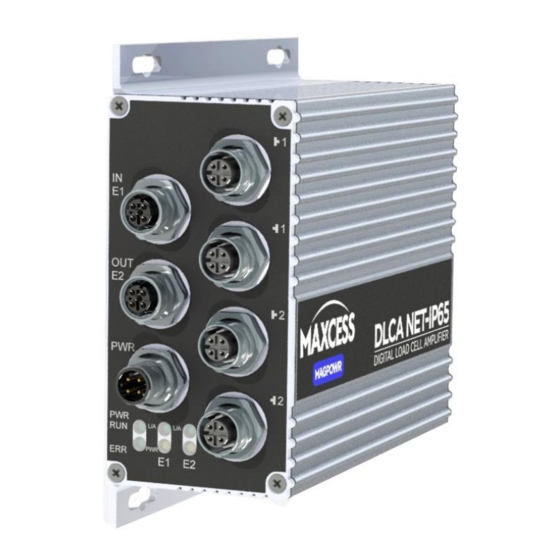
INSTALLATION Channel 1 load cell inputs Channel 2 load cell inputs Ethernet port 1 Ethernet port 2 Power Figure 2. DLCA NET-IP65-ECAT connector labels www.maxcessintl.com DLCA NET-IP65-ECAT MI 850A366 1 Page 12 of 44... -
Page 13: Cables Used On The Dlca Net-Ip65-Ecat
INSTALLATION Cables used on the DLCA NET-IP65-ECAT 3.3.1 Power cable The power cable has an M12 connector on one end and leads on the other end. Table 1shows the lengths available; the five meter length is standard. The maximum length is 50 meters. Length Length Model... -
Page 14: Ethernet Cable
INSTALLATION 3.3.3 Ethernet cable The Ethernet1 cable has an M12 connector on one end and an RJ-45 connector on the other end. Table 3 shows the lengths available; the five meter length is standard. Lengths above 60 meters are not recommended, but can be special ordered. -
Page 15: Led Indicators
LED INDICATORS 4.0 LED indicators The LEDs on the DLCA NET-IP65-ECAT provide status information. Figure 3. DLCA NET-IP65-ECAT LED indicators Power (Yellow) The power LED shows power good or a fault. If power is good and there are no faults, the power LED is on. If there is a fault detected, the power LED is flashing. -
Page 16: Communications Interface
COMMUNICATIONS INTERFACE 5.0 Communications interface An electronic datasheet is available for EtherCAT. Cyclic parameters The cyclic parameters are available to read tension and status from the DLCA NET-IP65-ECAT and to send commands and parameters to the DLCA NET-IP65-ECAT. RO = Read only WO = Write only uint16 = unsigned 16-bit integer int32 = signed 32-bit integer... -
Page 17: Actual Tension Data
COMMUNICATIONS INTERFACE Actual tension data Tension is read from the DLCA NET-IP65-ECAT in the four cyclic parameters Tension 1, Tension 2, Tension Sum, and Tension Difference. The tension value is a 32-bit signed integer and is scaled to be 160 times the Maximum Tension value ignoring the decimal point position set by parameter 0x207 or 0x217. -
Page 18: Status
COMMUNICATIONS INTERFACE Status The Status cyclic parameter shows power good, power failure errors, and load cell check errors. The lower 8 bits show power good or the power error. The upper 8 bits show the type of load cell check error that occurred. The load cell check only runs during power-up. -
Page 19: Command Interface
COMMUNICATIONS INTERFACE Command interface Command Request Commands are entered into the register. Command Parameters are read or written by a value in the Request Parameter. To write a parameter value, the value must be set in the Command Request Parameter before the Command Request is entered. -
Page 20: Command Request
COMMUNICATIONS INTERFACE 5.6.1 Command request Commands start at 0x0 and continue to 0x1FF. Parameters start at 0x200 and continue to 0x3FF. For parameters, add 0x1000 for a Write and 0x0000 for a Read to the parameter number. Command Read or write Command/parameter list WO = Write Only, RO = Read only, RW = Read and Write The parameter Class specifies which group this parameter... - Page 21 COMMUNICATIONS INTERFACE 0x00F Cal Output 2, 10V, 0% Function None N/A on IP65 0x010 Cal Output 2, 10V, 100% Function None N/A on IP65 0x011 Cal Output 2, 20mA, 0% Function None N/A on IP65 0x012 Cal Output 2, 20mA, 100% Function None N/A on IP65...
- Page 22 COMMUNICATIONS INTERFACE Configuration Tension 2 (Tension Zone 2) 0x217 DP Position Parameter Parm RW – int16 See 7.0 0x218 ADC PGA Gain Parameter LC Cal RW – int16 See 7.0 0x219 Tension Zero Offset Parameter LC Cal RW – int32 See 7.0 0x21A Cal Tension...
- Page 23 COMMUNICATIONS INTERFACE Output 2 0x23B 0 to 10V Zero Offset Parameter Out Cal RW – int16 N/A on IP65 0x23C 0 to 10V Gain Parameter Out Cal RW – int16 N/A on IP65 0x23D 0 to 10V Zero Offset User Parameter Parm RW –...
-
Page 24: Command Response
COMMUNICATIONS INTERFACE 5.6.2 Command response Command Response A command response will be returned in the register. The response consists of a message type, an error or message number and the request command code all OR’ed together. When reading a parameter the value of the parameter will be returned Command Response Parameter Command in the... -
Page 25: Function Information
COMMUNICATIONS INTERFACE Function information This section describes how the functions are used. 5.7.1 Security The DLCA NET-IP65-ECAT can be locked out to prevent parameter changes and calibrations from being performed. Setting or clearing security To set or clear the security state, two identical passwords must be entered using the command Password 1 Entry and Password 2 Entry. -
Page 26: Reset Non-Volatile (Nv) Memory To Defaults
COMMUNICATIONS INTERFACE 5.7.2 Reset non-volatile (NV) memory to defaults These commands will reset the specified parameters to factory defaults. Command Function Explanation Reset parameters belonging to the 0x019 Reset NV Parameters Only Parameter class. Reset NV Load Cell Reset parameters belonging to the 0x01A Calibrations Only Load Cell Calibration class. -
Page 27: Parameters
PARAMETERS 6.0 Parameters This section describes the parameters available in the DLCA NET-IP65-ECAT. Filtering The tension zone displays have a separate low pass filter. The communication tension values can use either the tension display filter or have no filtering. The tension display filter response can be set from 500 Hz to 0.01 Hz. The filters are a second order low pass filter for frequencies from 0.01 Hz to 124.99 Hz. -
Page 28: Alarm Setup And Operation
PARAMETERS Alarm setup and operation The following parameters describe the setup and operation of the alarms. Parameter Description Units Default Range 0x224 Tension Channel/Zone used for alarm IP65 1 0x22B IP65 1 {0, 2} 0 = Channel 1 1 = Channel 2 IP65 2 2 = Tension Sum {0, 1}... -
Page 29: Alarm Operation With Hysteresis
PARAMETERS 6.2.1 Alarm operation with hysteresis Alarm activation type 0 Alarm turns on when tension is greater than High value. Alarm turns off when tension is less than (HighValue – (HysteresisPercent * Maximum Tension)) Alarm activation type 1 Alarm turns on when tension is less than Low value. Alarm turns off when tension is greater than (LowValue + (HysteresisPercent * MaximumTension)) Alarm activation type 2... -
Page 30: Hardware Configuration Parameters
PARAMETERS Hardware configuration parameters These parameters configure the hardware or provide information about the hardware. Parameter Description Default 0x200 Zero Tension Lock Issuing a Zero Tension Zone 1 or Zone 2 command will immediately zero the tension value. It does not do a zero calibration, but just records the current offset signal and stores it for subtraction from the reading. - Page 31 PARAMETERS 0x204 Product Type Set by factory Indicates the product model of this hardware. 1 = DLCA NET1 2 = DLCA NET2 3 = DLCA NET-SLIM1 4 = DLCA NET-SLIM2 5 = DLCA NET-IP651 6 = DLCA NET-IP652 0x205 Program Version Set by factory The current version of software in this product 0x206...
-
Page 32: Calibration
CALIBRATION 7.0 Calibration The DLCA NET-IP65-ECAT has two modes of calibration: Precision and Weightless. Precision calibration is used when applying a known weight with a rope in the web path to the load cells for calibration. Typically this known weight should be 10% of the load cell rating or greater. -
Page 33: Figure 4. Apply Calibration Tension
CALIBRATION Precision calibration procedure continued When performing a calibration both the zero and precision calibrate steps must be done in sequence before a calibration is valid. If only zeroing the tension is required use the 0x1E or 0x1F command. Unload the load cell(s) for Tension Zone 1. Enter the command 0x01 (Zero Calibrate Zone 1) in the Command Request register. - Page 34 CALIBRATION Precision calibration procedure continued Tension Polarity If the calibration is successful, then (0x216 or 0x223) will automatically be set to show positive tension when force is applied in the direction of the calibration force. Configuration Tension 1 The following parameters in the group Configuration Tension 2 are set by the calibration procedure:...
-
Page 35: Weightless Calibration Procedure
CALIBRATION Weightless calibration procedure Enter values into the calibration parameters shown below. Refer to Figure 5 for the meaning of wrap angle and angle from force direction. Parameter Name and description Default Range 0x207 Decimal Point Position {0, 6} 0x217 Sets the decimal point position for the tension display. - Page 36 CALIBRATION Weightless calibration procedure continued When performing a calibration both the zero and WEIGHTLESS calibrate steps must be done in sequence before a calibration is valid. If only zeroing the tension is required use the 0x1E or 0x1F command. 1. Unload the load cell(s) for Tension Zone 1. 2.
-
Page 37: Figure 5. Weightless Calibration Angles
CALIBRATION If the returned tension values in the cyclic data are negative, you will need to manually set the Tension Polarity parameter (0x216 or 0x223) so that the tension values are positive. Configuration Tension 1 The following parameters in the group Configuration Tension 2 are set by the calibration procedure. -
Page 38: Calibration Errors Returned
CALIBRATION Calibration errors returned Value Error description and solution 0x00 Calibration was successful. No Errors found. Signal read by the amplifier is too large when maximum tension is applied. 0x01 This is caused by maximum tension being too large. Reduce maximum tension. -
Page 39: Web Server
WEB SERVER 8.0 Web server Access the web server in the DLCA NET-IP65-ECAT An Ethernet connection must be made to Ethernet Port 2 only. The DLCA NET-IP65-ECAT must be disconnected from the EtherCAT network and then power must be cycled. The DLCA NET-IP65-ECAT will allow non-EtherCAT traffic on Ethernet Port 2 after restarting as long as no EtherCAT traffic is detected on either Ethernet port. -
Page 40: Tension Calibration From Web
WEB SERVER Tension calibration from web pages To calibrate tension with the web pages edit the parameters below in the proper tension zone before performing the calibration commands. 8.1.1 Precision calibration from web pages Enter these parameters: Load Cell Excitation voltage (on Hardware web page) Which Sensor Inputs Used (on Hardware web page) Maximum Tension Calibration Tension... -
Page 41: Weightless Calibration From Web Pages
WEB SERVER 8.1.2 Weightless calibration from web pages Enter these parameters: Load Cell Excitation voltage (on Hardware web page) Which Sensor Inputs Used (on Hardware web page) Load Cell Sensitivity Load Cell Rating Maximum Tension Web Wrap Angle Angle from Force Direction Procedure 1. -
Page 42: Specifications
SPECIFICATIONS 9.0 Specifications Supply voltage range 24 VDC ±10% Proper earth grounding is required. Note that the negative supply and earth ground are interconnected on the product. The power supply must have an SELV output, such as Puls ML15.241, Mean Well MDR-20-24 or equivalent. -
Page 43: Service
Phone: 1.405.755.1600 Telefon: +49.6195.7002.0 Fax: 1.405.755.8425 Fax: +49.6195.7002.933 Web: www.maxcessintl.com Web: www.maxcess.eu When ordering replacement parts, please indicate, where possible, part number, drawing number and model description. If it is necessary to return this product for service, take care to properly package the unit to prevent damage during... - Page 44 AND AFRICA AND SE ASIA Tel +1.405.755.1600 Tel +86.756.881.9398 Tel +91.22.27602633 Tel +81.43.421.1622 Tel +49.6195.7002.0 asia@maxcessintl.com Fax +1.405.755.8425 Fax +86.756.881.9393 Fax +91.22.27602634 Fax +81.43.421.2895 Fax +49.6195.7002.933 www.maxcess.asia sales@maxcessintl.com info@maxcessintl.com.cn india@maxcessintl.com japan@maxcessintl.com sales@maxcess.eu www.maxcessintl.com www.maxcessintl.com.cn www.maxcess.in www.maxcess.jp www.maxcess.eu © 2018 Maxcess...
Need help?
Do you have a question about the MAGPOWR DLCA NET-IP65-ECAT and is the answer not in the manual?
Questions and answers