
Related Manuals for Seeed SENSECAP


Summary of Contents for Seeed SENSECAP
- Page 1 User Manual Sensor Hub - 4G Data Logger User Manual Version: V3 Page 1 of 45 © 2008-2021 Seeed Technology Co., Ltd. All rights reserved. solution.seeedstudio.com...
-
Page 2: Table Of Contents
Sensor Test ..........................31 5.2.5 Check & Confirm Data’s Upload to the Server ................31 Add Custom Measurement Types and Sensor Type IDs to the SenseCAP Cloud Platform ....34 Page 2 of 45 © 2008-2021 Seeed Technology Co., Ltd. All rights reserved. - Page 3 Low Temperature Environment Precautions (MUST-READ for Built-in Battery Version)....... 42 Aviation Connector Port Number (Wire Sequence) ................42 Installation Guide – Sensor Hub Data Logger ..................43 Installation Guide - Solar Panels ......................45 Page 3 of 45 © 2008-2021 Seeed Technology Co., Ltd. All rights reserved. solution.seeedstudio.com...
-
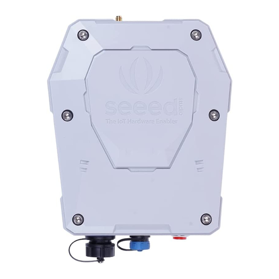
Page 4: Product Introduction
It has a maximal support for 32 sensors. The device uploads the collected data via 4G/3G/2G to user’s private MQTT server or to SenseCAP cloud. There are two types of power supply: wall power and solar power. With a built-in high-capacity rechargeable lithium battery, Sensor Hub can work for up to 2 weeks in rainy days or during power outage. - Page 5 Easy to maintain, supporting OTA for remote updates ⚫ Industrial-grade Environmental Tolerance: working temperature supporting -20℃ ~ +60℃ ⚫ IP66 rated, resistant to UV and rain erosion, suitable for outdoor applications System Architecture: Page 5 of 45 © 2008-2021 Seeed Technology Co., Ltd. All rights reserved. solution.seeedstudio.com...
-
Page 6: Quick Deployment Guide
1. Unpack, refer to the packing list and check whether there are missing parts. 2. Bind the device using the SenseCAP APP by scan the QR code on Sensor Hub. 3. Install the SIM card: Use the Allen Hex Key to open the cover of the device and insert the SIM card. -
Page 7: Connect Sensor Hub To 3Rd-Party Sensors And Servers
7. Check the sensor data on the server. 8. Deploy the device. 1) Check and confirm the location for installing the device. 2) Install poles, brackets, and sensors, etc. Page 7 of 45 © 2008-2021 Seeed Technology Co., Ltd. All rights reserved. solution.seeedstudio.com... -
Page 8: Assemble The Device
Device Packing List (Sensor Hub). Number Parts Number Sensor Hub Antenna Power Adapter USB Serial Tool Allen Hex Key and M5 Self-drilling Screw 1 / 8 Mounts Ferrules Aluminum Mounts Page 8 of 45 © 2008-2021 Seeed Technology Co., Ltd. All rights reserved. solution.seeedstudio.com... -
Page 9: Device Interface Introduction
Swipe downward to open the SIM card socket, insert the Micro SIM card and swipe upward to lock the SIM card socket. Make sure it is installed correctly and close the lid with the screws. Page 9 of 45 © 2008-2021 Seeed Technology Co., Ltd. All rights reserved. solution.seeedstudio.com... -
Page 10: Install The Antenna
3. Each interface must be connected to sensors of the same voltage. For example, you can connect four 5V sensors to B1 port, while connecting four 12V sensors to B2 port, but do NOT connect both 5V and 12V sensors to the same port. Page 10 of 45 © 2008-2021 Seeed Technology Co., Ltd. All rights reserved. solution.seeedstudio.com... -
Page 11: Configure Apn
Unscrew the protective cover of the power supply connector, plug one end of the power extension cord into the power connector and tighten it, plug the other end of the power extension cord directly into the power adapter. Page 11 of 45 © 2008-2021 Seeed Technology Co., Ltd. All rights reserved. solution.seeedstudio.com... -
Page 12: Configure The Device To Connect To Sensecap Cloud Platform
Android Bind Devices and Sensors to your Account Sign in to SenseCAP App with your account, select Binding in the upper right corner of the home page, scan the QR code on the device, and "confirm" the binding. Page 12 of 45 ©... -
Page 13: Prepare Tool
Prepare Tool 4.2.1 Sensor Hub Configuration Tool Download the Sensor Hub Configuration Tool from GitHub: https://github.com/Seeed-Solution/SenseCAP-Sensor-Hub-Configuration-Tool-NG/releases For MacOS, please install: SenseCAP-Sensor-Hub-Configuration-Tool-X.X.X dmg For Windows, please install: SenseCAP-Sensor-Hub-Configuration-Tool-X.X.exe Page 13 of 45 © 2008-2021 Seeed Technology Co., Ltd. All rights reserved. solution.seeedstudio.com... -
Page 14: Usb-To-Ttl Cable And Driver Installation
The aviation connect (blue part) is connected to the power port (B6) of Sensor Hub Data Logger and the USB port is connected to the computer. Install the driver: https://github.com/Jenkinlu001/SenseCAP/tree/master/Drivers Page 14 of 45 © 2008-2021 Seeed Technology Co., Ltd. All rights reserved. solution.seeedstudio.com... -
Page 15: Configuration Tool Introduction
User Manual Configuration Tool Introduction Access the SenseCAP Sensor Hub Configuration Tool on your computer: ① Select the serial port number. ② The device modes include: (1) Working mode and (2) Configuration Mode: Page 15 of 45 © 2008-2021 Seeed Technology Co., Ltd. All rights reserved. -
Page 16: Universal Settings
(3) Press the power switch to turn on the device. After booting, the "General Settings" button will light up, and the device’s information will be shown on the right side of the interface. Page 16 of 45 © 2008-2021 Seeed Technology Co., Ltd. All rights reserved. solution.seeedstudio.com... -
Page 17: Device Eui And Data Upload Interval Modifications
Device EUI: The device's unique number, corresponding to the device label, is 16 bits long. ② Card ICCID: SIM card ICCID (readable only in working mode). Signal RSSI: Cellular (readable only in working mode). Page 17 of 45 © 2008-2021 Seeed Technology Co., Ltd. All rights reserved. solution.seeedstudio.com... -
Page 18: Mqtt Server Configuration
(Change to upload data every 10 minutes) 4.4.2 MQTT Server Configuration When you access the General Settings, some commands are shown at the right window of the main interface. Page 18 of 45 © 2008-2021 Seeed Technology Co., Ltd. All rights reserved. solution.seeedstudio.com... - Page 19 (1) Select the cloud platform: Click to enter commands directly at the green cursor below the main interface. Enter the lowercase letter: b Input: 1 is the SenseCAP cloud platform (default); 2 is the user's third-party MQTT server; 3 is a SenseCAP private deployment;...
-
Page 20: Gps Configuration
After completing the parameters, make sure to click "Write". After configuring the server information, if you want to use the SenseCAP Cloud again, follow the similar method: In the main interface, type the command line: enter b => enter 1, and select SenseCAP Cloud Platform. 4.4.3 GPS configuration ④... -
Page 21: Apn Configuration
5 minutes depending on the type and number of sensors. The data can be viewed on the cloud platform, as shown below: Page 21 of 45 © 2008-2021 Seeed Technology Co., Ltd. All rights reserved. solution.seeedstudio.com... -
Page 22: View Data And Device Status On Sensecap Cloud Platform
Instructions for SenseCAP Cloud Platform The main function of SenseCAP Cloud Platforms is managing devices and data. The cloud service is built on a secure and reliable cloud services. Users can bind devices to a designated account for convenient management. SenseCAP provides a web portal and API data interface. -
Page 23: Api Instructions
User Manual API Instructions SenseCAP API is for users to manage IoT devices and data. It combines three types of API methods: HTTP protocol, MQTT protocol, and Websocket protocol. • With HTTP API, users can manage all devices, to get RAW data or historical data. -
Page 24: Add A Custom Sensor
After exiting the General Settings, press the device switch again to enter Sensor Settings. Once you have entered the configuration interface, click Read to get the current device configuration information. Page 24 of 45 © 2008-2021 Seeed Technology Co., Ltd. All rights reserved. solution.seeedstudio.com... -
Page 25: Sensor Categorization
(by default). And you can configure to enable or disable this function. When connected to a SenseCAP Modbus-RTU RS485 sensor, users do not need any configuration, just plug and play. SenseCAP sensors are industry-standard sensors, suitable for outdoor applications scenarios such as agriculture, cities, industry, and more. -
Page 26: Add A Custom Sensor (Example: Soil Temperature & Moisture Sensor)
Connect to Sensor Hub: Plug the aviation connector into any port (1 to 4) on Sensor Hub Data Logger. 5.2.2 Configure Sensors’ Basic Information (1) Read the information. Page 26 of 45 © 2008-2021 Seeed Technology Co., Ltd. All rights reserved. solution.seeedstudio.com... - Page 27 5V power supply, so select 5V here. ③ Power Time: Periodic: When Sensor Hub enters “Periodic” mode, the sensor’s power supply is cut-off, and Page 27 of 45 © 2008-2021 Seeed Technology Co., Ltd. All rights reserved. solution.seeedstudio.com...
-
Page 28: Configure Measurement Value
⑦ Startup Time: The length of time the sensor can communicate from powered -on to communicating with Modbus, unit: 100 milliseconds. 5.2.3 Configure Measurement Value (1) Select Sensor, and in the list of measured values, click on the"+" Page 28 of 45 © 2008-2021 Seeed Technology Co., Ltd. All rights reserved. solution.seeedstudio.com... - Page 29 2 decimal Value places, unit: °C 0-10000 Soil Moisture Divide by 10000 to get the actual INT16/ read-only Value humidity value, 2 decimal places, unit: % Page 29 of 45 © 2008-2021 Seeed Technology Co., Ltd. All rights reserved. solution.seeedstudio.com...
- Page 30 "06 00 00 00 00", the maximum support for command A is 10 bytes. Following the above method, add a soil moisture value and set the measurement ID to 5501: Page 30 of 45 © 2008-2021 Seeed Technology Co., Ltd. All rights reserved. solution.seeedstudio.com...
-
Page 31: Sensor Test
When finishing the testing on the software, turn off Sensor Hub and the Sensor Configuration Interface. (1) Uncheck " Enter configuration mode automatically on device's booted " . Page 31 of 45 © 2008-2021 Seeed Technology Co., Ltd. All rights reserved. solution.seeedstudio.com... - Page 32 After the device is working for a while, you can see the actual data and send prompts. For an explanation of the detailed log, you can view at the 7 chapter of Log Analysis. Page 32 of 45 © 2008-2021 Seeed Technology Co., Ltd. All rights reserved. solution.seeedstudio.com...
- Page 33 User Manual Now you can view the data on the SenseCAP cloud platform or your own server and confirm that the data is uploaded correctly. Page 33 of 45 © 2008-2021 Seeed Technology Co., Ltd. All rights reserved. solution.seeedstudio.com...
-
Page 34: Add Custom Measurement Types And Sensor Type Ids To The Sensecap Cloud Platform
(1) Once you're on the cloud platform, click "Custom Type" in the left function bar, and then click "Measurement". (2) In the case of soil temperature, for example, the soil temperature measurement ID is 5500, unit: °C Page 34 of 45 © 2008-2021 Seeed Technology Co., Ltd. All rights reserved. solution.seeedstudio.com... -
Page 35: Add Sensor Type
5.3.2 Add Sensor Type (1) Select the "Sensor Type". The sensor ID of soil temperature and moisture is defined as 6000, the measurement value is soil Page 35 of 45 © 2008-2021 Seeed Technology Co., Ltd. All rights reserved. solution.seeedstudio.com... - Page 36 Fill in sensor type ID:6000 and select the measurement (multiple options) in the list. (2) Complete adding the Type IDs. The measurement type, units, and so on are displayed for the added custom sensor. Page 36 of 45 © 2008-2021 Seeed Technology Co., Ltd. All rights reserved. solution.seeedstudio.com...
-
Page 37: Troubleshooting And Log Analysis
[ERROR] rs485 err code will appear in the window, and when collecting data, it will wait for the warm-up time before communicating to ensure that the right data can be obtained. Page 37 of 45 © 2008-2021 Seeed Technology Co., Ltd. All rights reserved. solution.seeedstudio.com... -
Page 38: Log Analysis
MCU reset reason: POR/PDR reset | SensorHub-2G/4G 2.0.2 Mar 1 2021 19:23:12 [2000/01/01 00:00:03] # Battery status[7268mv,57%,absent] # TEMP: 24.88 # APP VER: 2.0.2 # BOOT VER: 2.0.0 Page 38 of 45 © 2008-2021 Seeed Technology Co., Ltd. All rights reserved. solution.seeedstudio.com... - Page 39 16, saddr: 0, sensorID: 0x0000, status: IDLE channel: 17, saddr: 0, sensorID: 0x0000, status: IDLE channel: 18, saddr: 0, sensorID: 0x0000, status: IDLE channel: 19, saddr: 0, sensorID: 0x0000, status: IDLE Page 39 of 45 © 2008-2021 Seeed Technology Co., Ltd. All rights reserved. solution.seeedstudio.com...
- Page 40 Network latency: 92ms // network latency >ST APP OTA OTA elapse: 4s Log information for communication with the server >ST CONNECT SERVER [2021/03/08 17:05:59]need get token server_url: 39.108.230.236 server_port: 1883 Page 40 of 45 © 2008-2021 Seeed Technology Co., Ltd. All rights reserved. solution.seeedstudio.com...
- Page 41 This is the latest info, ver:2! elapse:3s >ST WORK LIST: # meas_count:1, unsent:0 # cycle:300s, work:146s, sleep:154s # net_reg:1, net_err:0, net_elapse:23s # average_work_tm:146s [2021/03/08 17:06:17]= === RUN END{1615194377}-0==== Page 41 of 45 © 2008-2021 Seeed Technology Co., Ltd. All rights reserved. solution.seeedstudio.com...
-
Page 42: Do's & Don'ts
Describe If the sensor is powered by 12v, connect this pin If the sensor is powered by 5v, connect this pin RS485 A RS485 B Ground Page 42 of 45 © 2008-2021 Seeed Technology Co., Ltd. All rights reserved. solution.seeedstudio.com... -
Page 43: Installation Guide - Sensor Hub Data Logger
(2) Install the hoops and mount the collector to the pole. (3) When connecting the aviation connectors, align the widest groove on the male head to the position of the flat head, insert and tighten. Page 43 of 45 © 2008-2021 Seeed Technology Co., Ltd. All rights reserved. solution.seeedstudio.com... - Page 44 If installing the devices outdoors for a long time, it is recommended to use a threaded tube to protect the exposed cables and increase their service life. Page 44 of 45 © 2008-2021 Seeed Technology Co., Ltd. All rights reserved. solution.seeedstudio.com...
-
Page 45: Installation Guide - Solar Panels
3. Sensor Hub Data Logger is installed under the solar panel to reduce the impact of direct sunlight on the equipment and increase the life of the equipment. Page 45 of 45 © 2008-2021 Seeed Technology Co., Ltd. All rights reserved. solution.seeedstudio.com...
Need help?
Do you have a question about the SENSECAP and is the answer not in the manual?
Questions and answers