Table of Contents
Advertisement
OPERATING AND MAINTENANCE MANUAL
Product:
Type:
DESIGNED AND MANUFACTURED BY:
T & R Test Equipment Limited
15-16 Woodbridge Meadows, Guildford, Surrey, GU1 1BJ, United Kingdom
Telephone: 01483 207428
Fax.:
01483 511229
Primary Current Injection System
PCU1-SP mk2
PCU1-LT mk2
1
e-mail:
sales@trtest.com
Web:
www.trtest.com
Advertisement
Table of Contents

Summary of Contents for T&R PCU1 Series
- Page 1 OPERATING AND MAINTENANCE MANUAL Product: Primary Current Injection System Type: PCU1-SP mk2 PCU1-LT mk2 DESIGNED AND MANUFACTURED BY: T & R Test Equipment Limited 15-16 Woodbridge Meadows, Guildford, Surrey, GU1 1BJ, United Kingdom Telephone: 01483 207428 e-mail: sales@trtest.com Fax.: 01483 511229 Web: www.trtest.com...
- Page 2 GENERAL SAFETY STATEMENT WARNING The following safety precautions should be reviewed to avoid injury to the user and damage to the product (and other products connected to it). To avoid potential hazards only use this product as specified. Only suitably qualified personnel should use this equipment. Servicing of this product should only be carried out by suitably qualified service personnel.
- Page 3 SAFETY TERMS AND SYMBOLS The following safety symbols appear on the equipment: CAUTION/WARNING – Refer to manual HOT – Refer to manual Mains off Mains on The following safety symbols appear in this manual: This action or procedure may be dangerous if not carried CAUTION out correctly and may cause damage to the equipment or connected equipment.
-
Page 5: Table Of Contents
CONTENTS DESCRIPTION OF EQUIPMENT Control Unit Front Panel Layout and Functions Loading Unit Front Panel Layout 1.2.1 NLU2000 & NLU5000 1.2.2 NLU200 Electrical Specification 1.3.1 Supply Requirements 1.3.2 Loading Unit Outputs 1.3.3 Secondary Injection Output (PCU1-SP only) 1.3.4 Metering 1.3.5 Timing System Displayed Values and Messages 1.4.1... - Page 6 2.2.1 Connections 2.2.2 Testing 2.2.3 After Testing Timing System 2.3.1 Timer Modes 2.3.2 General Procedure for Timing Tests APPLICATION NOTES – TESTING SPECIFIC DEVICES Secondary Injection of an Over-Current Relay (PCU1-SP only) 3.1.1 Timer Mode 3.1.2 Connections 3.1.3 Test Procedure Primary Injection of an Over-Current Relay (PCU1-SP &...
- Page 7 3.6.3 Test Procedure CT Polarity (PCU1-SP only) 3.7.1 Modes & Settings 3.7.2 Connections 3.7.3 Test Procedure CT Ratio (PCU1-SP only) 3.8.1 Modes & Settings 3.8.2 Connections 3.8.3 Test Procedure MAINTENANCE Output Control Brushes Removal of the PCU1 from Case STANDARD ACCESSORIES Spare Fuses Supplied: Standard Accessories Supplied: OVERALL PERFORMANCE SPECIFICATION...
-
Page 9: Description Of Equipment
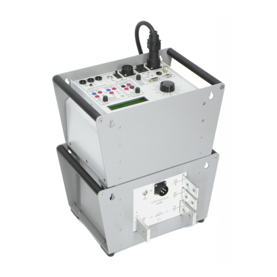
DESCRIPTION OF EQUIPMENT The PCU1 mk2 series are medium powered primary current injection systems offering output currents up to 5000A. The system consists of a separate control unit containing all metering and control functions and a loading unit that provides the high current output. The PCU1-LT mk2 and PCU1-SP mk2 are ideally suited to primary current injection, stability testing and circuit breaker testing. -
Page 10: Control Unit Front Panel Layout And Functions
Control Unit Front Panel Layout and Functions Figure 1.1 PCU1-SP mk2 front panel layout... - Page 11 UNIT ITEM FUNCTION TYPE Secondary Injection Output 0-100A Secondary injection output NLU metering connection Metering/control connection to loading unit Output circuit breaker Protection for primary current output Loading unit power connector Power supply to loading unit ...
-
Page 12: Loading Unit Front Panel Layout
Loading Unit Front Panel Layout The PCU1 system is available with a range of optional loading units and output lead sets. The loading unit is connected to the control unit using a metering cable and a power cable. Three output taps are provided for connection to the load. The load is connected between the common terminal and one of the output taps. -
Page 13: Nlu200
1.2.2 NLU200 ITEM FUNCTION PCU1 metering connection Metering/control connection to control unit Power connector Power supply from control unit Common output Output common terminal. One of the output leads is always connected to this terminal. Tap 1 output Highest current, lowest voltage output 200A 60V Tap 2 output Highest voltage, lowest current output... -
Page 14: Electrical Specification
Electrical Specification 1.3.1 Supply Requirements The PCU1 systems require a single phase 50/60Hz supply of 230V±10%. The maximum power requirement of the system depends on the level of current to be drawn from the control unit. For maximum output a 50A supply is required, but in most situations a 32A supply will suffice. -
Page 15: Loading Unit Outputs
1.3.2 Loading Unit Outputs Each loading unit has two or three output taps. The highest currents are available on the lowest voltage taps. Intermittent current Open Loading Continuous Circuit unit current 5 min on/ 1 min on/ 40s on/ Voltage 15 min off 15 min off 15 min off... -
Page 16: Secondary Injection Output (Pcu1-Sp Only)
1.3.3 Secondary Injection Output (PCU1-SP only) The PCU1-SP has a two-tap secondary injection output capable of injecting up to 100A without the use of a loading unit. The secondary injection output is selected using the metering range select switch. Current Unit Range Voltage... - Page 17 1.3.4.2 Secondary Injection Output Ammeter Ranges (PCU1-SP only) Ammeter Unit Accuracy Trip current range 10.00A ±0.5%rdg±5d 10.5A PCU1-SP 20.00A ±0.5%rdg±5d 100.0A ±0.5%rdg±5d 105A 1.3.4.3 Auxiliary Meter Ranges (PCU1-SP only) The PCU1-SP has an auxiliary metering input with 300V/5A inputs. This can additionally measure the phase angle between output current and auxiliary input or the ratio between output current and auxiliary current.
-
Page 18: Timing System
1.3.5 Timing System The PCU1 systems are fitted with an integrated timing system linked to the output and the two sets of contact inputs. The system is highly flexible, and allows for the timing of all common protection devices and trips. The timer may also be used to time external events not linked to the output of the set. -
Page 19: Displayed Values And Messages
Displayed Values and Messages 1.4.1 Displayed Values The PCU1 display simultaneously shows the injected test current, the loading unit metering range full scale, the timer result, the selected auxiliary input value and quantity (SP models only), and the state of the output on a liquid crystal display. It also displays warning and error messages, detailed in the following section. - Page 20 Remove Loading Unit Green to continue Figure 1.8 (PCU1-SP only) Secondary injection selected with loading unit power lead plugged in to PCU1 Connect Loading Unit Green to continue Figure 1.9 Primary injection selected with loading unit not connected Press Green to continue Figure 1.10 Loading unit fault cleared, waiting for user LU Over Temperature...
-
Page 21: Primary Current Injection Lead Sets
Primary Current Injection Lead Sets 1.5.1 Description Optional output lead sets are available to complement the PCU1 system. These lead sets are optimised to minimise impedance. Lead set Cross-sectional No. of leads area 200NAL 25mm 2000NAL 280mm 3000NAL 420mm 4000NAL 560mm The 2000NAL lead set consists of one pair of leads that are connected between the NLU and the load as shown in figure 1.11. -
Page 22: Factors Affecting Maximum Output Current
1.5.2 Factors Affecting Maximum Output Current The maximum output current obtainable from each tap of the loading unit output depends on the following factors: Lead impedance Lead length Load impedance The lead impedance is often dominant in defining the maximum current that may be injected into the load. -
Page 23: Lead Set Voltage Drops
1.5.3 Lead Set Voltage Drops Approximate voltage drops for the lead sets are shown below. Please note that the arrangement of the output leads has a very large effect on the output voltages available. Lead set CSA (mm Length Voltage drop Voltage drop Test current Leads... -
Page 24: Overload Protection
Circuit breaker Main output Circuit breaker Electronic over-current trip Electronic duty cycle trip Thermal protection Contact circuits Auto-resetting semiconductor fuses Auxiliary metering F6.3A fuse current input Construction The PCU1 series units are housed in robust aluminium cases fitted with lifting handles. -
Page 25: Installation
Ensure that the unit is connected to an appropriate supply by a suitably rated connector. WARNING The PCU1 series control units and NLU series loading units are heavy. Avoid lifting where possible. Ensure that two people are used to lift the units and that appropriate manual handling techniques are used. -
Page 26: Operation
OPERATION This chapter describes how to use the PCU1 systems in a variety of applications. Specific examples are given in the applications section. Primary Current Injection with Loading Unit The loading unit output from the PCU1 control unit is ONLY for connection to a T&R Test Equipment NLU series loading unit. -
Page 27: Testing
Connect the loading unit to the control unit as shown in figure 2.1. When switched on, the control unit will automatically detect the loading unit type. Set the metering range switch to 10%, 50% or 100%. These ranges refer to % of maximum rated current of the connected loading unit, so for an NLU5000 100% is 5000A and for an NLU2000 100% is 2000A. -
Page 28: Secondary Current Injection (Pcu1-Sp Only)
Secondary Current Injection (PCU1-SP only) The secondary current injection output of the PCU1-SP allows currents of up to 100A to injected for testing relays and trips. To use the secondary injection output the loading unit power lead must be disconnected and one of the secondary injection metering ranges selected. Figure 2.2 Secondary Injection Connections 2.2.1 Connections... -
Page 29: After Testing
2.2.3 After Testing On completion of the test, switch off the output using the “off” pushbutton. Return the output control to zero and switch off the supply. Before disconnecting the test object ensure the mains supply switch is in the OFF position. Timing System The PCU1 timing system is closely integrated with the main output and is very flexible. -
Page 30: Timer Modes
2.3.1 Timer Modes 2.3.1.1 Timer Mode: Off In the ‘off’ mode, the timer has no effect on the operation of the set, and the timer does not run. This mode is used to set the required current through the test object before a timing test. 2.3.1.2 Timer Mode: Internal Start The internal start mode starts the timer when the main output is switched on, and stops the timer on the first change of contact set 1. -
Page 31: General Procedure For Timing Tests
Approximate timer Loading unit Metering range Range full scale start/stop current None Secondary Injection 100A 100A 500A 100A NLU5000 2500A 500A 100% 5000A 1000A 200A NLU2000 1000A 200A 100% 2000A 400A NLU200 100A 100% 200A 2.3.1.6 Pulse Mode Pulse mode may be used to generate high current pulses into the test object. The electronic trips are disabled in pulse mode, and the output current is only limited by the circuit impedance. - Page 32 2.4.2.2 Testing It is advisable to make a preliminary test on the test object, starting at zero voltage, in order to test the load impedance, before performing the test with output control set at higher values. Therefore, ensure the output control knob is fully anti-clockwise before switching on. Ensure the timer mode switch is in the off position, and depress the on push-button.
-
Page 33: Application Notes - Testing Specific Devices
APPLICATION NOTES – TESTING SPECIFIC DEVICES Secondary Injection of an Over-Current Relay (PCU1-SP only) Figure 3.1 Secondary injection of over-current relay 3.1.1 Timer Mode Internal start 3.1.2 Connections Connect the relay current coil to the most appropriate output on the PCU1 (5V 100A or 15V 33A). -
Page 34: Primary Injection Of An Over-Current Relay (Pcu1-Sp & Lt)
When the device under test trips the timer will stop and the output will be switched off automatically. Primary Injection of an Over-Current Relay (PCU1-SP & LT) 3.2.1 Timer Mode Internal start 3.2.2 Connections Connect current output from loading unit to desired input on device under test. -
Page 35: Timing Of Auto-Reset/Reclosing Devices (Pcu1-Sp & Lt)
Timing of Auto-reset/Reclosing Devices (PCU1-SP & LT) 3.3.1 Timer Mode Single contact 3.3.2 Connections Connect current output from loading unit to desired input on device under test. Connect the trip contact on the relay under test to contact set 1 on the control unit. 3.3.3 Test Procedure Switch on the main supply... -
Page 36: Timing Devices With No Auxiliary Contacts (Pcu1-Sp & Lt)
Timing Devices with NO Auxiliary Contacts (PCU1-SP & LT) 3.4.1 Timer Mode Current Operated 3.4.2 Connections Connect current output from loading unit to desired input on device under test. 3.4.3 Test Procedure Switch on the main supply switch. Set timer mode switch to the off position. -
Page 37: Using The Control Unit As A Single Contact Timer (Pcu1-Sp & Lt)
Using the Control Unit as a Single Contact Timer (PCU1-SP & LT) 3.5.1 Timer Mode Single contact 3.5.2 Connections Connect contact to be timed to contact set 1. 3.5.3 Test Procedure Switch on the main supply switch. Set timer mode switch to the single contact position. Ensure that the output control is in the zero position. -
Page 38: Ct Polarity (Pcu1-Sp Only)
CT Polarity (PCU1-SP only) 3.7.1 Modes & Settings Timer mode: Off Auxiliary metering: CT polarity 3.7.2 Connections Connect current output from loading unit to busbar through CT primary (or loop lead through the CT). Ensure that CT P2 connects to COM terminal on loading unit. -
Page 39: Ct Ratio (Pcu1-Sp Only)
CT Ratio (PCU1-SP only) 3.8.1 Modes & Settings Timer mode: Off Auxiliary metering: CT ratio 1A or CT ratio 5A as appropriate to CT secondary. 3.8.2 Connections Connect current output from loading unit to busbar through CT primary (or loop lead through the CT). -
Page 41: Maintenance
MAINTENANCE The following actions should only be taken by suitably qualified and competent service personnel. Before removing the unit from its case, ensure that the unit is disconnected from the mains. Under no circumstances connect the unit to the mains whilst it is WARNING removed from its case. -
Page 43: Standard Accessories
STANDARD ACCESSORIES Spare Fuses Supplied: 1 off 20mm F6.3A 1 off 32mm T4A Standard Accessories Supplied: 5 metre long supply cable terminated at one end to suit the PCU1 control unit mains input. 5 metre long interconnecting lead terminated at both ends to supply power from the control unit to the loading unit. -
Page 45: Overall Performance Specification
OVERALL PERFORMANCE SPECIFICATION 6.1. Insulation Resistance at 1000V DC The insulation resistance will not be less than 10 megohms between mains input to frame and all isolated outputs, and all combinations of isolated output to isolated output. 6.2. Applied Voltage Test Mains input to frame and all isolated outputs 2kV RMS for 1 minute. -
Page 46: Secondary Injection Current Output (Pcu1-Sp Only)
6.3.2 Secondary Injection Current Output (PCU1-SP only) Ammeter Unit Accuracy Trip current range 10.00A ±0.5%rdg±5d 10.5A PCU1-SP 20.00A ±0.5%rdg±5d 100.0A ±0.5%rdg±5d 105A 6.3.3 Auxiliary Metering Input Auxiliary metering range Full scale Accuracy 300.0V RMS 300.0V ±0.7%rdg±5d 5.000A RMS 5.000A ±0.7%rdg±5d 6.3.4 Timing System Timer mode... -
Page 47: Revision
REVISION Product / Type: Primary Current Injection – PCU-LT/SP mk2 & NLU Loading Units File: PCU1-LT-SP mk2 manual v3.doc Author: I.D.W. Lake Issue / Date: 4 / 02/05/19 Modified By: K. Smith Checked By: G Biggs Date: 03/05/19... - Page 48 Drawings Required A3/001753 latest issue (PCU1-SP mk2) A3/001755 latest issue (PCU1-LT mk2)
Need help?
Do you have a question about the PCU1 Series and is the answer not in the manual?
Questions and answers