Table of Contents
Advertisement
Quick Links
Advertisement
Table of Contents

Related Manuals for OTIS OI-6000K NXP Series


Summary of Contents for OTIS OI-6000K NXP Series
- Page 3 INSTRUCTION MANUAL COMPLETELY BEFORE OPERATING OR SERVICING. DANGER DANGER: OTIS INSTRUMENTS INC. OI-6000K-X-X-X-NXP-X IS AN AMBIENT AIR TOXIC GAS SENSOR ASSEMBLY AND ONLY MONITORS IN THE IMMEDIATE VICINITY OF THE SENSOR HOUSING. A SITE SURVEY IS REQUIRED IN ORDER TO DETERMINE THE BEST PLACEMENT AND QUANTITY OF SENSOR ASSEMBLIES.
-
Page 4: Table Of Contents
TABLE OF CONTENTS TABLE OF CONTENTS PRODUCT OVERVIEW ............................1 INTRODUCTION ..............................1 PRODUCT SPECIFICATIONS ..........................2 SYSTEM DIAGRAMS ............................3 1.3.1 EXTERNAL SYSTEM DIAGRAM ........................... 3 1.3.2 INTERNAL SYSTEM DIAGRAM ..........................4 1.3.3 ASSEMBLY DIAGRAM ............................5 INSTALLATION AND START-UP .......................... 6 PRODUCT PLACEMENT ............................ - Page 5 TABLE OF CONTENTS OPERATION SETTINGS ............................. 36 POWERING THE DEVICE ........................... 36 4.1.1 POWERING OFF ..............................36 4.1.2 POWERING ON ..............................36 SENSOR CALIBRATION ............................. 37 4.2.1 NULLING THE SENSOR (AUTO NULL) ......................37 4.2.2 CALIBRATING THE SENSOR (MANUAL CAL)....................39 4.2.3 CALIBRATING THE SENSOR (AUTO CAL) .......................
-
Page 6: Product Overview
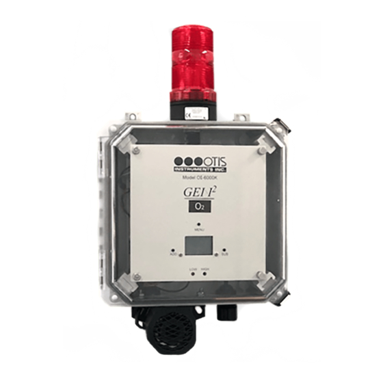
1 PRODUCT OVERVIEW 1.1 INTRODUCTION The Otis Instruments, Inc. (Otis) GEN II Model OI-6000K-X-X-X-NXP-X (OI-6000K) Non-Explosion-Proof Ambient Air Toxic Gas Detector is designed to detect a wide range of toxic gases in many environments excluding classified locations. The OI-6000K features a pre-mounted strobe light and dual tone horn. The strobe light can be selected to be Red, Amber, Blue, or a Tri-Color (Green/Amber/Red) LED. -
Page 7: Product Specifications
PRODUCT OVERVIEW 1.2 PRODUCT SPECIFICATIONS System Specifications Operating Voltage +12 to +35 VDC Current Draw 1.25 Amps Maximum Operating Temperature Range -20⁰C to +54⁰C Humidity Range 0% to 98% Relative Humidity, Noncondensing Measurement Range Varies based on gas type Response Time Varies based on gas type Protection Power Electromagnetic Interference (EMI) Filter... -
Page 8: System Diagrams
PRODUCT OVERVIEW 1.3 SYSTEM DIAGRAMS Refer to the following diagrams for identification of the external and internal system components that may be referred to in this manual. 1.3.1 EXTERNAL SYSTEM DIAGRAM 1 Strobe Light 2 Mounting Foot (4X) 3 Enclosure Latch (2X) Front Panel Thumb Screw (2X) 5 SUB Button... -
Page 9: Internal System Diagram
PRODUCT OVERVIEW 1.3.2 INTERNAL SYSTEM DIAGRAM RS-485 Modbus Terminal Block Fault Terminal Block Power Input/4-20mA Output Terminal Block Optional AC Power Supply Digital Sensor Board Cable and Connector Sensor Housing Interface Board Sensor Interface Adapter Board Wiring Terminal Block Relay 1 Terminal Block 10 Relay 2 Terminal Block 11 Digital Sensor Board Socket OI-6000K-X-X-X-NXP-X OPS_GUIDE_REV 1.0... -
Page 10: Assembly Diagram
PRODUCT OVERVIEW 1.3.3 ASSEMBLY DIAGRAM Strobe Light Enclosure Base Sensor Housing Base Sensor Element Sensor Housing Cap Electronics Assembly Gas Type Label Faceplate Assembly Enclosure Lid OI-6000K-X-X-X-NXP-X OPS_GUIDE_REV 1.0... -
Page 11: Installation And Start-Up
(1) the site/facility where the equipment is being installed and (2) the potentially present gas types and their dispersion. Otis strongly recommends that the end-user consults with the appropriate third-party Health, Safety and Environmental (HSE) and Industrial Hygiene (IH) professionals to determine the final quantity and placement of your gas detection devices. -
Page 12: Product Mounting
INSTALLATION AND STARTUP 2.2 PRODUCT MOUNTING It is recommended to mount the unit to a solid structure (such as a concrete wall, steel column, or angle iron) where a minimum of vibration will be transmitted to the unit. Alternately, a pole may be used along with a strap or a U-bolt, as long as it is rigid and of sufficient strength. -
Page 13: Opening The Enclosure
To provide DC power to the OI-6000K, you will need to connect the power cable from the sensor terminal block on an Otis monitor, or alternate user supplied power source, to the OI-6000K power terminal block located on the backplane of the enclosure. An electrician will need to install the proper cord grip for the cabling being used. - Page 14 To utilize the added functionality of the device, additional wiring is necessary. If an Otis Monitor is not used, the OI- 6000K can be powered from any +12 to +35 VDC power supply that can supply at least 1.250 Amps.
-
Page 15: Connecting 4-20 Ma Output
INSTALLATION AND STARTUP 2.3.3 CONNECTING 4-20 MA OUTPUT To utilize the 4-20 mA wired analog output feature of the OI-6000K, you will need to connect the signal cable from your monitoring device to the OI-6000K terminal block located on the backplane as well as a common ground reference wire. -
Page 16: Connecting Rs-485
The OI-6000K supports Modbus RTU over a RS-485 link. To integrate your device with RS-485 Modbus data communications, you will need to connect the Modbus cable from your Otis Monitor RS-485 input terminal block to the OI-6000 RS-485 output terminal block located on the control board of the unit. - Page 17 BROWN NOTICE If an Otis Monitor is not used, the OI-6000K can be connected to a Programmable Logic Controller (PLC) for RS-485 Modbus data communications. For integration and setup, refer to the Modbus Register Map found in Appendix C of this manual.
-
Page 18: Connecting Relays/Alarms
INSTALLATION AND STARTUP 2.3.5 CONNECTING RELAYS/ALARMS The OI-6000K relays are used to power and control the included strobe light and dual-tone horn. The strobe light and dual-tone horn are prewired from the factory and require no wiring by the end user. The following instructions are for reference if the strobe light or dual-tone horn need to be replaced in the field. - Page 19 INSTALLATION AND STARTUP CONNECTING OI-481-R/OI-481-A/OI-481-B STROBE LIGHT AND OI-488 HORN BACKPLANE WIRING OI-6000K OI-6000K TERMINAL BLOCK RELAY 1 TERMINAL RELAY 2 TERMINAL OI-481-X BLACK WIRE NEGATIVE OI-488 BLACK WIRE OI-481-X RED WIRE OI-488 RED WIRE POSITIVE BLUE BLUE OI-6000K-X-X-X-NXP-X OPS_GUIDE_REV 1.0...
- Page 20 INSTALLATION AND STARTUP 2.3.5.2 CONNECTING OI-481-RGA STROBE LIGHT AND OI-488 HORN – NON-O SENSORS On the OI-6000K Detector: 1. Locate the wiring terminal block on the backplane of the enclosure and complete the following: a. Connect a RED jumper wire to the positive supply terminal. b.
- Page 21 INSTALLATION AND STARTUP CONNECTING OI-481-RGA STROBE LIGHT AND OI-488 HORN – NON-O2 SENSORS BACKPLANE WIRING OI-6000K OI-6000K TERMINAL BLOCK RELAY 1 TERMINAL RELAY 2 TERMINAL OI-481-RGA BLACK OI-481-RGA GREEN & WIRE NEGATIVE BLUE WIRE OI-488 BLACK WIRE OI-481-RGA YELLOW OI-481-RGA RED WIRE WIRE POSITIVE OI-488 RED WIRE...
- Page 22 INSTALLATION AND STARTUP 2.3.5.3 CONNECTING OI-481-RGA STROBE LIGHT AND OI-488 HORN – O SENSORS On the OI-6000K Detector: 1. Locate the wiring terminal block on the backplane of the enclosure and complete the following: a. Connect a RED jumper wire to the positive supply terminal. b.
- Page 23 INSTALLATION AND STARTUP CONNECTING OI-481-RGA STROBE LIGHT AND OI-488 HORN – O2 SENSORS BACKPLANE WIRING OI-6000K OI-6000K TERMINAL BLOCK RELAY 1 TERMINAL RELAY 2 TERMINAL OI-481-RGA BLACK BLUE OI-481-RGA GREEN & WIRE NEGATIVE BLUE WIRE OI-488 BLACK WIRE OI-481-RGA YELLOW OI-481-RGA RED WIRE WIRE POSITIVE...
-
Page 24: Connecting The Fault Terminal
INSTALLATION AND STARTUP 2.3.6 CONNECTING THE FAULT TERMINAL The fault terminal is used to provide indication of a device failure. The fault terminal is shipped configured as a normally-closed (NC), or fail-safe, configuration, terminating power to the external fault device when prompted, changing this behavior is detailed in the product settings and configuration section of this manual. -
Page 25: Closing The Enclosure
During warmup, the display will show a countdown of the time remaining until the system start-up is complete. The Otis logo and the unit information will also show on the display screen during start- At the end of the countdown, the device will be in normal operating mode. -
Page 26: Normal Operating Mode
INSTALLATION AND STARTUP 2.5 NORMAL OPERATING MODE During normal operating mode, the OI-6000K continuously samples the air and updates the measured concentration of the target gas on the display screen. The display, when in normal operation, appears as shown below. ④... -
Page 27: Product Settings And Configuration
PRODUCT SETTINGS AND CONFIGURATION 3 PRODUCT SETTINGS AND CONFIGURATION The product settings and configuration menu allows the end-user to tailor the device settings to meet their required specifications and/or site conditions. The product settings and configuration menu consist of the following screens: Relay Test ◼... -
Page 28: Performing The Relay Test
PRODUCT SETTINGS AND CONFIGURATION 3.1.1 PERFORMING THE RELAY TEST The relay test gas level reading can be increased or decreased in increments of 5% of the sensor scale, up to 100% of the sensor scale. 1. Press the ADD button until the low and high alarm levels are reached and the relay(s) are triggered to light all visual alarm(s) and sound all audio alarm(s) on the monitor. -
Page 29: Null/Calibration Timer Information
PRODUCT SETTINGS AND CONFIGURATION 3.3 NULL/CALIBRATION TIMER INFORMATION The null/calibration time information screen allows the end-user to view the following information: The days since the sensor assembly was last nulled, only updates while the unit is turned on. ◼ The days since the sensor assembly was last calibrated, only updates while the unit is turned on. ◼... -
Page 30: Latching And Non-Latching Relay Settings
PRODUCT SETTINGS AND CONFIGURATION 3.5 LATCHING AND NON-LATCHING RELAY SETTINGS Relay 1 and Relay 2 can be set to latching or non-latching. Relays set to non-latching will automatically deactivate when the detected gas level falls below the corresponding alarm setting. Conversely, latching relays, once activated, MUST be manually reset at the device, regardless of the change in gas detection level readings. -
Page 31: Relay 2: Latching/Non-Latching Setting
PRODUCT SETTINGS AND CONFIGURATION 3.5.2 RELAY 2: LATCHING/NON-LATCHING SETTING 1. Use the ADD and SUB buttons to toggle between the “UnLatch” and “Latch” options. 2. Press the MENU button to select the desired setting and to advance to the Relay 1 fail-safe setting screen. -
Page 32: Relay 1: Fail-Safe Setting
PRODUCT SETTINGS AND CONFIGURATION If the fault terminal cannot be used, Otis Instruments recommends one of the following configurations: Recommended Configurations for Relay Fail-Safe Setting Power Source Relay Wiring Fail-Safe Outcome OI-6000K Normally-Closed (NC) No (Off) Normal Operation: Closed Alarm Activation: Open... -
Page 33: Fault Terminal Fail-Safe Setting
PRODUCT SETTINGS AND CONFIGURATION 3.7 FAULT TERMINAL FAIL-SAFE SETTING The Fault Terminal Fail-Safe status behavior can be adjusted to either activate during a fault condition or deactivate during a fault condition. The default setting is to deactivate during a fault condition, this setting should only be adjusted if the opposite behavior is desired. -
Page 34: Modbus Address Setting
1 to 247 available for your device. The RS-485 Modbus communication parameters used in Otis devices is 8 data bits, no parity, and 1 stop bit; these parameters are fixed and cannot be changed. The floating point data values are presented with the least significant bytes first. -
Page 35: Modbus Baud Setting
For successful communication, the baud rate setting of the OI-6000K MUST match the baud rate setting on the attached Otis Monitor, or other Modbus device. All Otis devices have factory default Modbus baud settings of 9600 bps. The RS-485 Modbus communication... -
Page 36: Ma Offset Settings
Setting the 4-20 mA offset allows the end-user to calibrate the sensor’s analog output. Upon installation of the device, if the detected gas reading on OI-6000K does not correspond to the reading on the Otis Monitor, or other monitoring device, the zero offset (4 mA) and the full-scale offset (20 mA) can be adjusted on the unit. -
Page 37: Full-Scale Offset Setting
1. Use the ADD and SUB buttons to increase and decrease the full-scale offset, respectively, until the Otis Monitor reads the full scale value for that channel. 2. Press the MENU button to save the desired setting and to advance to the display screen contrast setting screen. -
Page 38: Return To Factory Default Settings
PRODUCT SETTINGS AND CONFIGURATION 3.13 RETURN TO FACTORY DEFAULT SETTINGS Returning the OI-6000K to its factory default settings will reset all customization of the device, including the null and calibration settings of the sensor element. OI-6000K Product and Configuration Factory Default Settings Configuration Setting Relay Test... - Page 39 PRODUCT SETTINGS AND CONFIGURATION 1. Press the ADD button to select “Yes” to return the device to its factory default settings and to advance to the return to factory default settings confirmation screen. If you do not wish to return the device to its factory default settings, press the SUB button to select “No”...
-
Page 40: Reset Null & Calibration Values
PRODUCT SETTINGS AND CONFIGURATION 3.14 RESET NULL & CALIBRATION VALUES Resetting the null and calibration settings of the sensor element will allow the currently stored null and calibration values to be rest without having to reconfigure all of the other operational settings like with the Return to Factory Defaults option. -
Page 41: Operation Settings
During the 1-minute warmup, the display will show a countdown of the time remaining until the system start-up is complete. The Otis logo and the unit information will also flash on the display screen and, at the end of the countdown, the device will be in normal operating mode. -
Page 42: Sensor Calibration
4.2 SENSOR CALIBRATION Calibration is the process of evaluating and adjusting the precision and accuracy of measurement equipment. Although Otis calibrates every device at the factory, for best accuracy, the detector SHOULD be calibrated in the environment where it is installed. - Page 43 OPERATION SETTINGS 3. Press the ADD button to select “Yes” to confirm that the sensor is in clean air and to begin nulling the sensor. If the sensor is not in clean air, press the SUB button to select “No” to discontinue the null process and to return to the previous screen.
-
Page 44: Calibrating The Sensor (Manual Cal)
OPERATION SETTINGS 4.2.2 CALIBRATING THE SENSOR (MANUAL CAL) You should ONLY perform the calibration of the sensor after the null process has been completed. For best results, use 50% of the sensor scale of your target gas in an air balance with a flow rate of 0.25 to 0.5 LPM. -
Page 45: Calibrating The Sensor (Auto Cal)
OPERATION SETTINGS 4.2.3 CALIBRATING THE SENSOR (AUTO CAL) You should ONLY perform the calibration of the sensor after the null process has been completed. For best results, use 50% of the sensor scale of your target gas in an air balance with a flow rate of 0.25 to 0.5 LPM. - Page 46 OPERATION SETTINGS 5. Affix a regulator to the calibration gas bottle. 6. Attach the tubing on the Calibration Adapter Kit to the regulator on the calibration gas bottle. 7. Ensure that the gas is flowing and press the MENU button to begin calibrating the sensor, the unit will automatically begin the calibration process, the amount of time on the timer will vary based on the gas type.
-
Page 47: Sensor Alarm Settings
OPERATION SETTINGS 4.3 SENSOR ALARM SETTINGS The OI-6000K has two alarm settings: LOW alarm and HIGH alarm. All alarm set-points are field adjustable up to 60% of the full-scale gas concentration. The factory default setting on the OI-6000K for the LOW alarm is 10% of full scale and 15% of full scale for the HIGH alarm. -
Page 48: Sensor Low Alarm Rise/Fall Setting
OPERATION SETTINGS 4.3.2 SENSOR LOW ALARM RISE/FALL SETTING 1. Use the ADD and SUB buttons to select between activation on a Rising or a Falling gas level, respectively. 2. Press the MENU button to save the desired setting and to advance to the sensor HIGH alarm setting screen. -
Page 49: Sensor High Alarm Rise/Fall Setting
OPERATION SETTINGS 4.3.4 SENSOR HIGH ALARM RISE/FALL SETTING 1. Use the ADD and SUB buttons to select between activation on a Rising or a Falling gas level, respectively. 2. Press the MENU button to save the desired setting and to advance to setting the radio address (if you have a radio module installed), otherwise you will return to Normal Operating Mode. -
Page 50: Product Maintenance
5 PRODUCT MAINTENANCE 5.1 SCHEDULED MAINTENANCE Otis recommends that our equipment be calibrated a MINIMUM of every 90 days, and STRONGLY advise that calibration be performed every 30 days. Without knowing the specific application, sensor assembly location, gas exposure, and other factors, the company recommends monthly calibrations – assuming no damage or potential damage has occurred to the sensor and that there has not been a power outage to the sensor assembly. -
Page 51: Sensor Replacement
The sensor elements used in the OI-6000K detects gas in either % or PPM concentrations, this element must be fully functional in order for the system to operate correctly. Otis recommends replacing the sensing element whenever a slow response to gas is observed during the normal calibration process. After replacing the sensing element the device MUST then be nulled and calibrated for proper operation of the device. - Page 52 PRODUCT MAINTENANCE 4. Plug in the new sensing element into the sensor housing board. Ensure that the pins on the sensing element align with the sockets on the sensor housing board. 5. Screw the sensor housing cap back onto the sensor housing base, ensuring that the sensor housing cap is only tightened hand tight.
-
Page 53: Product Troubleshooting
PRODUCT MAINTENANCE 5.3 PRODUCT TROUBLESHOOTING OI-6000 Fault Codes Problem Cause(s) Solution(s) 1. The control board has lost communication 1. Check connection between the sensor with the digital sensor interface adapter board. housing connector header and the digital Check sensor interface adapter board plug-in. Sensor 2. -
Page 54: Product Replacement Parts And Accessories
5.4 PRODUCT REPLACEMENT PARTS AND ACCESSORIES While not all the components on the OI-6000K can be field-replaced, there are several parts that are replaceable by an Otis Approved Service Technician. To purchase accessories/replacement parts for your device, contact the sales representative of this product for assistance. - Page 55 INTRODUCTION TO 4-20 mA CURRENT LOOP SIGNALS APPENDIX B: MODBUS COMMUNICATIONS APPENDIX C: MODBUS REGISTER MAP APPENDIX D: OTIS INSTRUMENTS PRODUCT WARRANTY STATEMENT APPENDIX E: INFORMATION ABOUT RMA SERVICE REPAIRS APPENDIX F: INFORMATION ABOUT RMA RETURNS FOR CREDIT OI-6000K-X-X-X-NXP-X OPS_GUIDE_REV 1.0...
-
Page 56: Appendix A: Introduction To 4-20 Ma Current Loop Signals
20 mA the highest. The relationship between the current loop and the gas value is linear. In addition, Otis devices use values below 4 mA to indicate special status conditions, as shown... - Page 57 APPENDICES Sensor Element Scale Ranges Sensor Type Gas Type Formula Range Electrochemical (EC) Hydrogen Sulfide 0-100 PPM Electrochemical (EC) Hydrogen Sulfide (High Range) H2S2K 0-2000 PPM Electrochemical (EC) Sulfur Dioxide 0-20 PPM Electrochemical (EC) Oxygen 0-25 % Electrochemical (EC) Carbon Monoxide 0-1000 PPM Electrochemical (EC) Chlorine...
-
Page 58: Appendix B: Modbus Communications
A daisy chain is a wiring scheme in which multiple devices are wired together in a sequence, or in a ring. Daisy chains may be used for power, analog signals, digital data, or a combination thereof. For the purposes of Otis devices, the term daisy chain refers to multiple devices connected in a series to form a single long line of devices, connected via the wiring patterns embedded within each device. - Page 59 APPENDICES The signal wire of each unit is run to the signal terminal of the neighboring sensor. With each device connected to the previous device via the signal wire, a “chain” is created, with the first device in the chain directly connected to the monitor.
-
Page 60: Appendix C: Modbus Register Map
APPENDICES APPENDIX C: MODBUS REGISTER MAP OI-6000 FAMILY MODBUS REGISTER MAP Register Register Address Address Data Description Length Unit Valid Response(s) (Hex) (Dec) Gas Reading FLOAT Numerical Gas Reading Modbus Address UINT 0 – 247 Gas Type ENUM 0 – 26, see below Unit Type ENUM 0 –... - Page 61 APPENDICES OI-6000 MODBUS REGISTER MAP ENUMERATION KEYS Register Address 4: Gas Type Administrator Mode Register Address B/11: Fault Code Response Gas Type Response Fault Type H2S – Hydrogen Sulfide No Fault SO2 – Sulfur Dioxide Loss of Communication with O2 – Oxygen Sensor Board CO –...
-
Page 62: Appendix D: Product Warranty Statement
(g) damage, caused by product modifications, alterations of functionality or capability; (h) defects, caused by normal wear and tear or otherwise due to the normal aging of the Otis product, or (i) any product in which a product-labeled serial number has been removed, defaced, or altered in any way. - Page 63 Otis Warranty service, at their discretion, will (a) repair the device using new or previously used parts that are equivalent to new in performance and reliability, (b) replace the Otis Product with a device that is at least functionally equivalent to the Otis product and is formed from new and/or previously used parts that are equivalent to new in performance and reliability, or (c) exchange the Otis Product for a refund of your purchase price, when an Otis Product is submitted.
-
Page 64: Appendix E: Information About Rma Service Repairs
All RMA Service repairs are treated as quick-return exchanges. Otis Instruments, Inc. does not replace board level components (i.e. magnetic switches, resistors, capacitors, relays, etc.). There is no charge for RMA Service repairs that are within the specified warranty period. For a copy of the Otis Instruments, Inc. - Page 65 If advanced replacement is required, please contact the Service Department for more information. INTERNATIONAL RMA SERVICE REPAIRS The customer is responsible for complying with all import/export requirements for shipment of RMA/Service repairs to Otis Instruments, Inc. OTIS INSTRUMENTS RMA SERVICE DEPARTMENT Otis Instruments / Repairs 301 South Texas Ave. Bryan, Texas 77803 Office: 979.776.7700...
-
Page 66: Appendix F: Information About Rma Returns For Credit
IMPORTANT INFORMATION All RMA Returns for Credit must be shipped to OTIS Instruments / RMA Returns, 301 S. Texas Avenue, Bryan, Texas 77803. Product/part returns must be in their original condition and packaging, as shipped from the manufacturer. Returns that do not meet these specifications will be rejected for return for credit. - Page 67 APPENDICES Notes: OI-6000K-X-X-X-NXP-X OPS_GUIDE_REV 1.0...
- Page 68 Otis Instruments 301 S. Texas Avenue, Bryan, Texas 77803 Tel: 979.776.7700 Fax: 979.776.7719 sales@otisinstruments.com service@otisinstruments.com www.otisinstruments.com...
Need help?
Do you have a question about the OI-6000K NXP Series and is the answer not in the manual?
Questions and answers