
Summary of Contents for Lenze BFK457 Series
- Page 1 BA 14.0164 399 720 GB Operating Instructions K14.0609 K14.0610 Spring-operated brakes with electromagnetic release Type BFK457- PP...
- Page 2 The data indicated in the product key and on the nameplate and stickers on the packaging are valid for spring-operated brakes of the series BFK457. These Operating Instructions are valid for the following spring-operated brakes: BFK457-03 BFK457-04 BFK457-05 BFK457-06 BFK457-08 Author: Lenze GmbH & Co KG, Brakes 2nd edition: 07/00 BA BFK457 GB 2.0...
- Page 3 Nameplate Layout Field 1 Field 2 Field 3 Assembly Field Contents Example Manufacturer Brake type Order no. BFK457 03 Nr 391935 BFK457-03 Nr.391935 Rated voltage Rated power Rated brake torque/CE mark 205V DC 9W 205V DC 9W 0,5NM 0,5NM 70815 Date of manufacture Packaging sticker Layout...
-
Page 4: Table Of Contents
..............1.3 Lenze drive systems . - Page 5 Contents 6 Maintenance / repair ........... . 6.1 Inspection intervals .
-
Page 6: Preface And General Information
After reception of the delivery, check immediately whether the scope of supply matches with the accompanying papers. Lenze does not accept any liability for deficiencies claimed subsequently. Claim – visible transport damage immediately to the forwarder. -
Page 7: Lenze Drive Systems
– disregarding these Instructions. Warranty Warranty conditions: see Sales and Delivery Conditions of Lenze GmbH & Co KG Brakes. Warrenty claims must be made immediately after detecting defects or faults. The warranty is void all cases where liability claims cannot be made. -
Page 8: Safety Information
(see IEC 364, definition for qualified personnel). General safety information These safety notes do not claim to be complete. In case of questions and problems please contact your Lenze representative. At the time of supply the spring-operated brake is state-of-the-art and ensures basically safe operation. -
Page 9: Layout Of The Safety Information
Safety information Possible applications of the spring-operated brake BFK457-PP: No explosive or agressive atmostphere. Humidity, no restriction. Ambient temperature -20EC bis +40EC. With high humidity and low temperatures – Take measures to protect armature plate and rotor from freezing. Electrical connections must be protected against contact. Layout of the safety information All safety information given in these Operating Instructions has the same layout: Signalword! -
Page 10: Technical Data
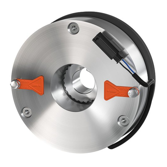
Technical data Technical data Product description Stator Sticker - nameplate Armature plate Spring Countersunk screw DIN7500 Rotor with friction lining Cover seal Flange Socket head screws DIN 912 K14.0607 FIG. 1 Spring-operated brake: BFK457-03...05 Stator Sticker - nameplate Armature plate Spring Cap screws Rotor with friction lining... -
Page 11: Braking
Technical data 3.1.2 Braking When braking, the rotor (2.0), which is moveable on the hub (3.0), is pressed against the friction surface by the central spring (size 03...05) or the inner and outer springs (1.4) (sizes 06+08) via the armature plate (1.2). The asbestos-free friction linings ensure a high brake torque with low wear. The brake torque is transmitted between hub (3.0) and rotor (2.0) via the splines. - Page 12 Technical data BA BFK457 GB 2.0...
-
Page 13: Switching Times
Technical data Type Brake torque Friction work with Transition Switching times [s] Spark suppressor Rated value at one switching frequency at s Lürated ∆n= 100min ∆n= 100min operation operation hü hü Order number DC engagement Separation [Nm] BFK457-03 0.009 0.006 0.015 0.016 BFK457-04... -
Page 14: Operating Frequency / Friction Work
Technical data Engagement time With switching on the AC side, the engagement times are prolonged extremely. They are approx. 10 times longer, connection see FIG. 11. With the simplest connection of rectifier and brake directly parallel to the motor winding, the engagement times are prolonged because the motor is switched off but still rotating so that the brake is excited further. -
Page 15: Emission
Technical data Emission Electromagnetic compatibility For normal circuits with unsmoothed DC voltage via bridge connection, the spring-operated brake type BFK457-PP complies with thge electromagnetic compatibility EN50081 Teil 1. Please note, that the entire circuit only complies with the EMC Directive, if it is configured according to one of the following possibilities: Circuit: Rectifier... -
Page 16: Installation
Installation Installation Warning! Toothed hub or screws must not be lubricated with grease or oil. Required tools Wrench Type Torque wrench Insert for hexagon socket BITS-holder Insert for recessed head screws screws (Bits Phillips-recess) Opening Opening Opening Measuring range Opening [mm] [Inch] [Inch]... -
Page 17: Assembly
Installation Assembly Preparation 4.2.1 1. Unpack spring-operated brake. 2. Check for completeness 3. Check nameplate data, especially rated voltage. Installation Installation of the hub onto the shaft 4.3.1 Circlip 10.0 10.0 Endshield K14.0611 FIG. 5 Installation of the hub onto the shaft 1. -
Page 18: Installation Of The Brake Bfk457-03
Installation 4.3.2 Installation of the brake BFK457-03...05 Spring-operated brake 10.0 10.0 Endshield K14.0609 K140611/1 FIG. 6 Installation of the brake 1. Hub (3.0) installation, chapter 4.3.1. 2. Push spring-operated brake (1.0) onto the hub (3.0) FIG. 6 3. Bolt the spring-operated brake (1.0) to the endshield using the fixing screws (8.1) FIG. 6 4. -
Page 19: Installation Of Cover Seal For Brake Sizes 06+08
Installation Spring-operated brake 10.0 10.0 Endshield 12.0 Torque wrench 12.0 K14.0616/1 FIG. 8 4. Tighten the screws (8.1) evenly (for torques see the table Rated data, chapter 3.2 and FIG. 8. 4.3.4 Installation of cover seal for brake sizes 06+08 Stator 10.0 Armature plate... -
Page 20: Electrical Connection
Installation Electrical connection Warning! The brake must only be electrically connected when no voltage is applied. ¥ Bridge rectifier ¥ K14.0525 FIG. 10 Switching parallel to motor, extremely delayed engagement ¥ Bridge rectifier ¥ K14.0525/2 FIG. 11 DC switching delayed engagement BA BFK457 GB 2.0... - Page 21 Installation ¥ Bridge rectifier ¥ K14.0525/7 FIG. 12 DC switching, normal engagement ¥ DC voltage (e.g. 24V) ¥ ¦ Spark suppressor Connection diagram also valid for star connection ¦ K14.0525/3 FIG. 13 Separated DC voltage, DC switching. BA BFK457 GB 2.0...
-
Page 22: Commissioning And Operation
– unusual noises and temperatures – loose fixing elements – the state of the cables. In the event of failures, refer to the trouble shooting table in chapter 7. If the fault cannot be eliminated, please contact the Lenze Service. BA BFK457 GB 2.0... -
Page 23: Maintenance / Repair
Maintenance Maintenance / repair Inspection intervals The wear of the friction lining of the rotor depends of the operating conditions. The running time of the brake depends on the friction work per switching operation and on the differential speed. The inspection intervals must be adapted to the operating conditions and can be prolonged if the brake shows minimum wear. -
Page 24: Air Gap
Maintenance 6.2.2.2 Air gap Warning! The motor must be at standstill when checking the air gap. 1. Measure the air gap s between armature plate and stator using a feeler gauge. Lü 2. Compare the measured air gap with the maximum permissible air gap s . -
Page 25: Maintenance Of Brake Bfk457-06+08
Maintenance 6.3.2 Maintenance of brake BFK457-06+08 6.3.2.1 Re-adjustment of air gap Warning! Switch off the voltage. The brake must be free of residual torque. 11.0 Spring-operated brake Socket head screws ¥ 11.0 Feeler gauge 12.0 Torque wrench ¥ Lü rated 12.0 K14.0615 FIG. -
Page 26: Spare-Parts List
Maintenance Spare-parts list Only parts with order numbers available. The order numbers are only valid for standard versions. Bore diameter in mm Standard keyway to DIN 6885/1 P9 Size 03...05 Size 06+ 08 K14.0613 K14.0612 FIG. 15 Spare parts for spring-operated brakes BFK Size 03...08 Pos. -
Page 27: Order Of Spare Parts
Maintenance Order of spare parts 6.5.1 Spring-operated brake BFK457 Lenze GmbH & Co KG Bremsen Receiver: P . O. Box: 10 13 52 Postal code/City: D-31763 Hameln Fax No.: (049) 51 54 / 82-1107 Sender Company ____________________________________ Customer No. _______________________ Street / P .O. -
Page 28: Troubleshooting And Fault Elimination
Troubleshooting and fault elimination Troubleshooting and fault elimination Fault Cause Remedy Spring-operated brake does not release,air Coil is interrupted Measure the coil resistance using a multimeter: gap is not zero – If the resistance is too high, replace the spring- operated brake. -
Page 29: Declaration Of Conformity/Manufacturer's Certification
Declaration of Conformity/Manufacturer’s Certification Manufacturer’s Certification Brakes and clutches Lenze GmbH & Co KG Bremsen for the purpose of the EC Machinery Directive (98/ 37/ EG) Postfach 10 13 52 D-31763 Hameln We herewith certify that the below listed products are intended for assembly into a machine or for assembly with other elements to form a machine. - Page 30 Wülmser Weg 5 compliance with the above-mentioned EC Directive under the sole D-31855 Aerzen resposibility of Telephone (05154) 82-0 Telefax (05154) 82-11 07 Lenze GmbH & Co KG Bremsen, Postfach 10 13 52, D-31763 Hameln Product: Type: Electromagnetically released BFK454- BFK457-...
Need help?
Do you have a question about the BFK457 Series and is the answer not in the manual?
Questions and answers