Table of Contents
Advertisement
Quick Links
INSTALLATION MANUAL AND
OPERATING INSTRUCTIONS
MD41-244
MD41-248
Mid-Continent Instruments and Avionics
th
9400 E. 34
Street N., Wichita, KS 67226 USA
Phone 316-630-0101 Fax 316-630-0723
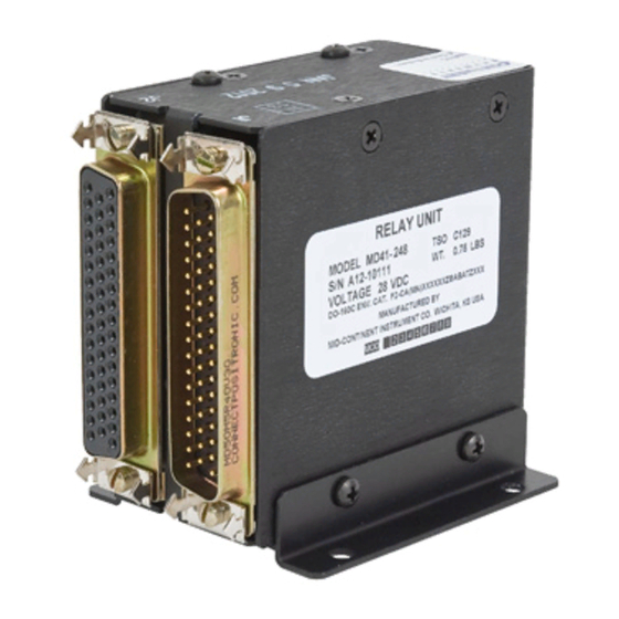
MD41-244/248 RELAY UNIT
14vdc
24 Pole, 14 volt operation
28vdc
24 pole, 28 volt operation
Manual Number 7019029
Rev. C Oct. 12, 2020
Advertisement
Table of Contents

Subscribe to Our Youtube Channel
Summary of Contents for Midcontinent MD41-244
- Page 1 INSTALLATION MANUAL AND OPERATING INSTRUCTIONS MD41-244/248 RELAY UNIT MD41-244 14vdc 24 Pole, 14 volt operation MD41-248 28vdc 24 pole, 28 volt operation Mid-Continent Instruments and Avionics Manual Number 7019029 9400 E. 34 Street N., Wichita, KS 67226 USA Rev. C Oct. 12, 2020...
-
Page 2: Revision Detail
REVISION DETAIL ECO Rev. Date Detail 08/22/97 Revised DO-160C section 5.0 environmental test data. Test category C is now category B. 5566 03/09/11 Revised Sec. 1.1 & 1.2.4 to indicate relay pairing and interlock failure monitoring by means of power being applied to activating coils. - Page 3 INSTALLATION CONSIDERATIONS COOLING EQUIPMENT LOCATION ROUTING OF CABLES LIMITATIONS SECTION 3 INSTALLATION PROCEDURE GENERAL INFORMATION UNPACKING AND INSPECTING MOUNTING THE MD41-244/248 INSTALLATION LIMITATIONS SECTION 4 POST INSTALLATION CHECKOUT PRE-INSTALLATION TEST OPERATING INSTRUCTIONS FIGURE N0. LIST OF ILLUSTRATIONS 3.1A, B, C...
-
Page 4: Section 1 General Description
(This feature provides indication that all relays have power applied to their activating coils. It does not monitor all relay contacts or coils.) A special ILS override that will automatically force the MD41-244/248 to switch to NAV mode when the NAV (VOR) receiver is tuned to an ILS frequency (optional connection). -
Page 5: Environmental Characteristics
ILS Override Receives a logic low from the NAV (VOR) J1 Pin 16 receiver when tuned to an ILS frequency. This will force the MD41-244/248 into NAV mode, regardless of the NAV/GPS selection. This connection is optional. Dimming Output Provides an adjustable dim voltage to be used J2 Pin 33 with a remote mounted annunciation unit. -
Page 6: Equipment Limitations
Annunciation Control Unit (ACU) in order to be approved as a complete TSO system. These items will not be TSO’d if one is installed without the other. NOTE: Any time the MD41-244/248 relay transfer unit is disconnected or removed from the aircraft, the HSI/CDI will be inoperative in both NAV (VOR) and GPS modes. -
Page 7: Section 2 Installation Considerations
ACU which now provides more options for panel mounting. ROUTING OF CABLES Care must be taken not to bundle the MD41-244/248 logic and low level signal lines with any high energy sources. Examples of these sources include 400 HZ AC, Comm, DME, HF and transponder transmitter coax. -
Page 8: Section 3 Installation Procedures
Mounting brackets for rear mount. MCIA PN 8012379 (2 required) MOUNTING THE MD41-244/248 The MD41-244/248 is provided with mounting rails that will allow mounting on the side, rear or with flat side down. Locate an area large enough to facilitate mounting of unit with connector and back shell in place. - Page 9 FIGURE 3-1A OUTLINE DRAWING VERTICAL MOUNT Manual Number 7019029 Rev. C Oct. 12, 2020...
- Page 10 FIGURE 3-1B OUTLINE DRAWING HORIZONTAL MOUNT Manual Number 7019029 Rev. C Oct. 12, 2020...
- Page 11 FIGURE 3-1C OUTLINE DRAWING REAR MOUNT Manual Number 7019029 Rev. C Oct. 12, 2020...
- Page 12 FIGURE 3-2 MATING CONNECTOR LAYOUT Manual Number 7019029 Rev. C Oct. 12, 2020...
- Page 13 FIGURE 3-3 SCHEMATIC DIAGRAM, MD41-244/248 24 POLE RELAY UNIT Manual Number 7019029 Rev. C Oct. 12, 2020...
-
Page 14: Section 4 Post Installation Checkout
J1 pin 33. Using an ohm meter, verify J2 pin 50 is aircraft ground. OPERATING INSTRUCTIONS Turn off the avionics master switch and connect the mating connector to the MD41-244/248. Turn on the avionics master switch and verify the NAV/GPS annunciators transfer correctly with the appropriate switch selection. -
Page 15: Environmental Qualification Form
ENVIRONMENTAL QUALIFICATION FORM RTCA / DO-160C NOMENCLATURE: MD41-244/248 RELAY UNIT TSO C129 CLASS A1 MODEL NO: MD41-244/248 MANUFACTURER TEST SPECIFICATION: MPS 7015613 MANUFACTURER: Mid-Continent Instruments and Avionics 9400 E. 34 Street N. Wichita, KS 67226 Phone (316) 630-0101 Conditions Section... - Page 16 Environmental Qualification (cont.) Conditions Section Description of Conducted Tests Sand and Dust 12.0 Equipment identified as Category X, no test required Fungus 13.0 Equipment identified as Category X, no test required Salt Spray 14.0 Equipment identified as Category X, no test required Magnetic Effect 15.0 Equipment tested to Class Z...
Need help?
Do you have a question about the MD41-244 and is the answer not in the manual?
Questions and answers