
Related Manuals for HESCH HE 5411

Summary of Contents for HESCH HE 5411
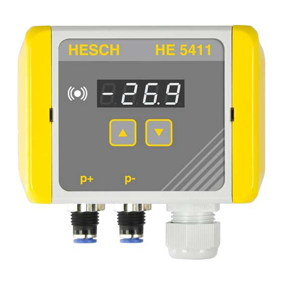
- Page 1 HE 5411 Differential pressure transducer with limit signal Operating Instructions (Translation of Original German version) # 340411 | Version 1.7...
- Page 2 Editor: HESCH Industrie-Elektronik GmbH, Documentation Department Copyrights © Copyright 2020 HESCH Industrie-Elektronik GmbH. All rights reserved. The content including pictures and the design of these operating instructions are subject to copyright protection and other laws for the protection of intellectual property. The operating instructions may only be distributed as a complete document and only with reference to the source.
- Page 3 21.10.2020 / 1.6 Chapter 10 Error messages: Error E.CAL, E. Sen. and E.Par added after software modifications Chapter 3 Technical data: sensor with ± 350 08.12.2020 / 1.7 mbar measuring range added / Bg HE 5411 Operating Instructions #340411 | version 1.7...
-
Page 4: Table Of Contents
OUNTING THE DEVICE DEVICE DESCRIPTION ..........................15 ........................15 UMMARY OF DEVICE VERSIONS 5.1.1 HE 5411 Lite (without limit signal) ....................15 5.1.2 HE 5411 Basic (without limit signal) ..................... 15 5.1.3 HE 5411 Premium (with limit signal) ..................... 15 ELECTRICAL COMMISSIONING ........................ -
Page 5: Legal Provisions
HESCH Industrie-Elektronik GmbH, Boschstraße 8, 31535 NEUSTADT, GERMANY Intended use The HE 5411 differential pressure transducer is a universal pressure transducer, mainly used in dedusting technology. It can also be used in the measurement of overpressure in clean rooms. -
Page 6: Safety Information
Indicates a potentially hazardous medium risk situation, which, if not avoided, could result in death or serious injury. CAUTION! Indicates a hazardous low risk situation, which, if not avoided, could result in minor or moderate injury. HE 5411 Operating Instructions #340411 | version 1.7... -
Page 7: Safety In The Individual Operating Phases
(in Germany VDE 0100). The measuring lines must be laid separately from the mains leads. Explosion Prevention! HE 5411 Lite, Basic and Premium with a supply voltage of 19…36 V DC are suitable for use in explosion zones 2 and 22, provided that the lid is closed. -
Page 8: Device Identification
Device Identification Note! The HE 5411 differential pressure transducer is available in three different designs. The corresponding device identification can be seen on the nameplate. Devices with a measuring range of ± 1.25 mbar (regardless of the device version) do not have any ATEX certification! - Page 9 Cleaning is necessary to prevent increased dust generation on the device. Operation under voltage, in zone 22 and 2, only in closed state. Before closing, ensure that the device housing is free of dust. HE 5411 Operating Instructions #340411 | version 1.7...
-
Page 10: Technical Data
RL ≥ 1 kΩ RA ≤ 500 Ω load Relay output 1 changeover contact 250 VAC, 5 A as limit value relay Service interface USB / TTL adapter HE 5851 required (see chapter 11 Accessories) HE 5411 Operating Instructions #340411 | version 1.7... - Page 11 Flexible wire size with ferrule without 0.2 mm²…1.5 mm² plastic sleeve Flexible wire size with ferrule with plastic 0.2 mm²…0.75 mm² sleeve Extras Special characteristics Free from silicone Silicone is not used in the production process. HE 5411 Operating Instructions #340411 | version 1.7...
- Page 12 Power supply 19…36 V DC 100…240 V AC 19…36 V DC 100…240 V AC MTTF without limit without limit signal with limit signal with limit signal signal Without 1090 display With display anno HE 5411 Operating Instructions #340411 | version 1.7...
-
Page 13: Mounting
EX ATEX Zones must be observed (see chapter 2.3 Safety in the individual operating phases) Note! A drill template can be found on the internet on: www.hesch.de. When you print it, please ensure to print out Document 1:1. Ensure the size accuracy of the print-out before drilling. -
Page 14: Opening The Device
The screwless hinge closure is recommended for rapid service access. Open the housing lid to the left. (The illustration does not show the HE 5411, but one with a structurally identical housing. The opening principle is identical.) Mounting the device 4 screws are required to fasten the device to the wall. -
Page 15: Device Description
0(4)…20 mA or 0…10 V. The 4-digit 7-segment display also allows the display of negative pressures. Summary of device versions 5.1.1 HE 5411 Lite (without limit signal) Front view HE 5411 Lite 5.1.2 HE 5411 Basic (without limit signal) Front view HE 5411 Basic 5.1.3 HE 5411 Premium (with limit signal) -
Page 16: Electrical Commissioning
Electrical Commissioning HE 5411 differential pressure transducer, 24 V DC (interior view) Note! Before commissioning, please note the information on the nameplate! HE 5411 Operating Instructions #340411 | version 1.7... -
Page 17: Electrical Connections
The power supply must correspond to the voltage indicated on the nameplate. The device may only be operated in closed condition. The temperature restrictions specified for the use of the device must be observed before and during operation. HE 5411 Operating Instructions #340411 | version 1.7... -
Page 18: Assembly Of Measuring Hose Onto Pressure Connection
Hose connection Insert hose with 6 mm outer diameter into the connection. Hose disconnection 1. Press the blue retaining ring to open the lock. 2. Pull the hose out of the connection. HE 5411 Operating Instructions #340411 | version 1.7... -
Page 19: Display And Operating Elements
Display and Operating Elements HE 5411 Premium Display and Operating Elements (outside and inside) 0(4)…20 mA switch LEDs Test button Rotary coding switch HE 5411 Operating Instructions #340411 | version 1.7... - Page 20 Lights up when the differential pressure measured is ≥ the limit value set Flashes when the device is in test mode TEST button for zeroing / Test mode Rotary coding switch, 16 levels (0…F) to set the measuring range. HE 5411 Operating Instructions #340411 | version 1.7...
-
Page 21: Limit Led
If the status display shows a red/yellow light, this means that the measured pressure is over the limit value and inside the set hysteresis range. HE 5411 Operating Instructions #340411 | version 1.7... -
Page 22: 7.1.2 "Limit Window" Mode
If the status display shows a red/yellow light, this means that the measured pressure is over or under the limit values and inside of the set hysteresis range. HE 5411 Operating Instructions #340411 | version 1.7... -
Page 23: Operation
% from the sensor measuring range to the zero point in order to achieve a successful zeroing. 1 × long A long press on the button resets the offset with respect to the zeroing to 0 mbar. HE 5411 Operating Instructions #340411 | version 1.7... -
Page 24: Offset For Zeroing With Device Keypad (He 5411 Premium)
Offset for zeroing with device keypad (HE 5411 Premium) Should a zeroing need to be carried out, a warm-up time of 30 minutes must be observed. Press buttons UP and DOWN. The current pressure at the pressure connections will be accepted as the offset. The measured pressure must be in the range of ±10 % from the... -
Page 25: Limit Value Parameter Setting With Device Keypad (He 5411 Premium)
Limit value parameter setting with device keypad (HE 5411 Premium) The 7-segment display shows the current actual value. Hold the UP button pressed down for 3 seconds to edit the upper limit value. Hold the DOWN button pressed down for 3 seconds to edit the lower limit value. -
Page 26: Analogue Output Setting
50 % bidirectional, square rooted 100 % unidirectional, square rooted 80 % unidirectional, square rooted 50 % unidirectional, square rooted Free (100 % bidirectional) pressure Free (100 % bidirectional) pressure Free (100 % bidirectional) pressure HE 5411 Operating Instructions #340411 | version 1.7... -
Page 27: Test Mode
300 s to nought and the word “TEST” are shown alternately on the 7-segment display. The red LED flashes! Pressing the “TEST” button again ends the Mode immediately, before the countdown from 300 s is over. HE 5411 Operating Instructions #340411 | version 1.7... -
Page 28: Parameter Setting With Service Pc
The “EasyTool Controls” software from Version 4.x is required to set the parameters with a service PC. The USB/TTL adapter required for that purpose is available from HESCH (see chapter 11 Accessories). The program allows a configuration to be saved, or a saved configuration to be established again. -
Page 29: Parameter Table
0% is displayed. Measuring range end Sensor Base measuring range end Min…Sensor Max The measuring range end indicates the pressure at which an output signal of 100% is displayed. HE 5411 Operating Instructions #340411 | version 1.7... - Page 30 Signal 30”. Base Output Signal 1 0…100 Base Input Signal 1 Sensor mbar Min…Sensor Max … 0…100 Base Output Signal 30 Base Input Signal 30 Sensor mbar Min…Sensor Max 2…30 Number of bases HE 5411 Operating Instructions #340411 | version 1.7...
- Page 31 Display / Output signal Input Example for damping a fluctuating signal Damping × 5 Input Display / Output signal Example for step response HE 5411 Operating Instructions #340411 | version 1.7...
- Page 32 Min…Sensor Max, basic measuring range end set on the device itself. See chapter 7.1 mbar, Pa, inH2O, psi Upper hysteresis limit value 1% of See chapter 7.1 basic measuring range end HE 5411 Operating Instructions #340411 | version 1.7...
- Page 33 If the upper or lower limit value is overshot or underrun, the relay is de-energised (see Figure 17). None Step (threshold = 10) Creep flow suppression ‘Step’ HE 5411 Operating Instructions #340411 | version 1.7...
- Page 34 Upper limit value Hysteresis over limit value Outer Hysteresis under limit value Lower limit value Relay control “Fail-Safe Relay” Inner Parameter = inactive “Fail-Safe Relay” Parameter = active Inner Configuration of the Limit Value HE 5411 Operating Instructions #340411 | version 1.7...
- Page 35 Device settings 50…100 Display brightness 000…999 Password The password must be entered using the UP and DOWN buttons before the parameters “Upper limit value” or “Lower limit value” can be set. HE 5411 Operating Instructions #340411 | version 1.7...
-
Page 36: Error Messages
The stored parameters are not valid (e.g. after a firmware the software “EasyTool Controls” update) Or set a parameter at the device , e.g. ‘Zeroing’ or ‘Limit’ alternating with the process value or displayed value. HE 5411 Operating Instructions #340411 | version 1.7... -
Page 37: Accessories
Accessories HESCH offers a series of optional accessories in connection with the assembly and connection technology of the HE 5411 differential pressure transducer: Item Picture Name Order number Wall bracket upon request as an alternative means of fastening the HE 5411 housing... - Page 38 Item Picture Name Order number Multiple sealing insert upon request 3 x cables Ø 5 mm USB/TTL adapter # 61000011 Incl. connection cable and “EasyTool Controls” PC software HE 5411 Operating Instructions #340411 | version 1.7...
-
Page 39: Maintenance And Service
Dispose of assembled printed circuit boards professionally. Service HESCH Industrie-Elektronik GmbH Boschstraße 8 31535 NEUSTADT GERMANY Phone: +49 5032 9535-0 Fax: +49 5032 9535–99 Internet: www.hesch.de Email: info@hesch.de HE 5411 Operating Instructions #340411 | version 1.7...
Need help?
Do you have a question about the HE 5411 and is the answer not in the manual?
Questions and answers