Table of Contents
Advertisement
Quick Links
Advertisement
Table of Contents

Summary of Contents for IRONRIDGE GROUND MOUNT
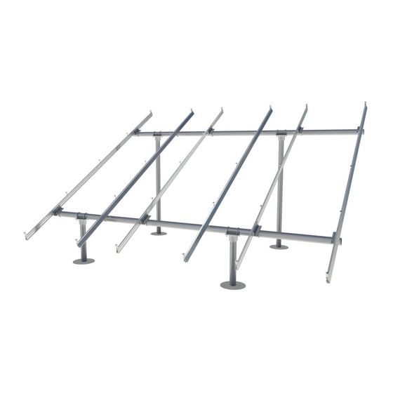
- Page 1 GROUND MOUNT INSTALLATION MANUAL...
-
Page 2: Table Of Contents
Comply with all applicable local or national building and fire codes, including any that may supersede this manual. • Ensure all products are appropriate for the installation, environment, and array under the site’s loading conditions. • Use only IronRidge parts or parts recommended by IronRidge; substituting parts may void any applicable warranty. • Review the Design Assistant Certification Letters to confirm design specifications. -
Page 3: Ratings
• Not Fire Rated STRUCTURAL CeRTIFICATION • Designed and Certified for Compliance with the International Building Code & ASCE/SEI-7 MARKINGS Product markings are located on the system’s Rail Connectors. © 2019 IRONRIDGE, INC. VERSION 2.8 GROUND MOUNT INSTALLATION MANUAL - 2... -
Page 4: Checklist
Grounding Lug, end Clamps, and expansion Joints please refer to Alternate Components Addendum (Version 1.60). ➢ If installing on a low slope roof please refer to Ground Mount for Flat Roof Applications Addendum (Version 2.60). Frameless Module Kit Frameless End/Mid Clamp ©... -
Page 5: Build Base
Brace piers until concrete foundation has cured. ➢ In some cases, cross bracing is required to provide extra support Concrete for piers. If required, install Diagonal Braces at this time. Foundation Depth 1/3 Depth © 2019 IRONRIDGE, INC. VERSION 2.8 GROUND MOUNT INSTALLATION MANUAL - 4... -
Page 6: Build Base
Check with your local jurisdiction for frost line embedment requirements. ➢ Friction Bolt must be IronRidge supplied M16-2.0 x 40mm hot-dip galvanized bolts. 2. CONNeCT SUBSTRUCTURe A. MOUNT TOP CAPS Mount a Top Cap on each pier. -
Page 7: Place Rails
Grounding Lugs can be installed anywhere along the rail and in (84 in-lbs) either orientation shown. ➢ Grounding Lugs are intended to for use with one solid or stranded copper wire, conductor size 10-4AWG. © 2019 IRONRIDGE, INC. VERSION 2.8 GROUND MOUNT INSTALLATION MANUAL - 6... -
Page 8: Secure Modules
Page 7 for CAMO installation procedure. D. RePeAT STePS Secure remaining module rows, leaving a minimum 3/8” gap between rows. ➢ If using end Caps, refer to Page © 2019 IRONRIDGE, INC. VERSION 2.8 GROUND MOUNT INSTALLATION MANUAL - 7... -
Page 9: Camo
For installations with Hanwha Q CeLLS modules with 32 mm frame heights, the maximum ground snow is 45 PSF (33 PSF module pressure). ➢ CAMO is not compatible with Canadian Solar modules. © 2019 IRONRIDGE, INC. VERSION 2.8 GROUND MOUNT INSTALLATION MANUAL - 8... -
Page 10: Electrical Diagram
Enphase or the AC module cable system for Sunpower via their integrated EGC. Plan View Only one Grounding Lug required per continuous subarray. Bonding Points Fault Current Ground Path Section View © 2019 IRONRIDGE, INC. VERSION 2.8 GROUND MOUNT INSTALLATION MANUAL - 9... -
Page 11: Diagonal Braces (Optional)
Wire Clips offer a simple wire management solution. Press Clip Snap Clip into Slot Closed Firmly press Wire Clip into top rail slot. Open clip and insert electrical wire accordingly. Close clip once complete. © 2019 IRONRIDGE, INC. VERSION 2.8 GROUND MOUNT INSTALLATION MANUAL - 10... -
Page 12: Splicing Cross Pipe
OR TOP CAP WITH A MAXIMUM GAP OF 1/2” ➢ To avoid potential problems from the effects of thermal expansion, a maximum total continuous cross pipe length of 100 ft is recommended. © 2019 IRONRIDGE, INC. VERSION 2.8 GROUND MOUNT INSTALLATION MANUAL - 11... -
Page 13: Microinverter Kits
MLPE mounting flange. Some will require 1 kit and others 2 kits. IronRidge systems using approved Enphase products or SunPower modules eliminate the need for lay-in lugs and field installed equipment grounding conductors (EGC). This solution meets the requirements of UL 2703 for bonding and grounding and is included in this listing. -
Page 14: Systems Using Microstorage Products
Sunpreme silver or black mid and end clamps with part numbers 7500105X where “X” is 1, 5, 6 or 7. Ironridge IronRidge silver or black mid and end clamps with part numbers FMLS-XC-001-Y where “X” is E or M and “Y” is B or blank. Module Clamp ➢... -
Page 15: Module Compatibility
MODULe COMPATIBILITY The Ground Mount System may be used to ground and/or mount a PV module complying with UL 2703 only when the specific module has been evaluated for grounding and/or mounting in compliance with the included instructions. Unless otherwise noted, “xxx” refers to the module power rating and both black and silver frames are included in the certification. - Page 16 Where “Y” can be A, D, M or S; and “ZZ” can be GI, HG, HI, KI, MI, MF, MG, PI, RI, RG, RG(BF), RG(BK), SG, TI, or TG © 2019 IRONRIDGE, INC. VERSION 2.8 GROUND MOUNT INSTALLATION MANUAL - 15...
- Page 17 Philadelphia modules with 35 and 40 mm frames Philadelphia Solar PS-YzzAA-xxx Where “Y” can be M or P; “zz” can be 60 or 72; and “AA” can be blank or (BF) © 2019 IRONRIDGE, INC. VERSION 2.8 GROUND MOUNT INSTALLATION MANUAL - 16...
- Page 18 SolarWorld Sunmodule Plus, Protect, Bisun, XL, Bisun XL, may be followed by mono, poly, duo, black, bk, or SolarWorld AG clear; modules with 31, 33 or 46 mm frames SW-xxx © 2019 IRONRIDGE, INC. VERSION 2.8 GROUND MOUNT INSTALLATION MANUAL - 17...
- Page 19 Where "y" can be either P or T; "Z" can be either M, P, or MX; and "a" can be blank or 6 Yingli Panda, YGE, YGE-U, and YLM series modules with 35, 40, and 50 mm frames © 2019 IRONRIDGE, INC. VERSION 2.8 GROUND MOUNT INSTALLATION MANUAL - 18...
-
Page 20: Framless Module Compatibility
Where “YY” can be blank or SL Trina Trina frameless modules TSM-xxxYY Where “YY” can be either DEG5(II), DEG5.07(II), DEG5.40(II), DEG5.47(II), DEG14(II), DEG14C(II), DE- G14C.07(II), DEG14.40(II), PEG5, PEG5.07, PEG5.40, PEG5.47, PEG14, or PEG14.40 © 2019 IRONRIDGE, INC. VERSION 2.8 GROUND MOUNT INSTALLATION MANUAL - 19...
Need help?
Do you have a question about the GROUND MOUNT and is the answer not in the manual?
Questions and answers