Advertisement
Quick Links
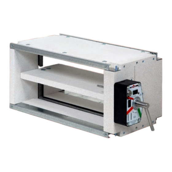
The space-saving solution
Maintenance-free
FK90K fire dampers
■ Sizes 100 x 100 to 800 x 250
■ Exceptionally high volume flows - Minimum pressure drop - Extremely quiet
■ For universal use with a wide range of applications
■ Fire classification: EI 30/60/90 (v
- h
, i ↔ o) S C
e
o
10ooo
■ Hygiene certificate
■ Environmental Product Declaration according to ISO 14025 and EN 15804
The German original version of this document shall prevail
User Manual 5.1-1 (2018-09) 1
Advertisement

Summary of Contents for Wildeboer FK92K Series
- Page 1 The space-saving solution Maintenance-free FK90K fire dampers ■ Sizes 100 x 100 to 800 x 250 ■ Exceptionally high volume flows - Minimum pressure drop - Extremely quiet ■ For universal use with a wide range of applications ■ Fire classification: EI 30/60/90 (v , i ↔ o) S C 10ooo ■ Hygiene certificate ■ Environmental Product Declaration according to ISO 14025 and EN 15804 The German original version of this document shall prevail User Manual 5.1-1 (2018-09) 1...
-
Page 2: Features And Characteristics
FK90K fire dampers Features and characteristics Casing made of calcium silicate Nominal width B: 100 mm to 800 mm Nominal height H: 100 mm to 250 mm Length: 260 mm Leak tightness class C according to EN 1751 Damper blade can be installed both horizontally and vertically - replaceable - Elastomer lip seal - frictionless sealing All-round enclosed thermal release elements 70°C or 95°C Large free cross-section Fully enclosed: Option: Maximum volume flow •... - Page 3 FK90K fire dampers Description Maintenance-free FK90K fire dampers according to EN 15650 Additional national approvals in Germany: Fire classifications: EI 30/60/90 (v , i ↔ o) S C • Building materials: Z-56.4212-993 10ooo Declaration of performance: FK90K fire dampers are essen- DoP no.: CPR/FK90K/002 tially made from non-combustible Environmental Product Declaration ISO 14025, EN 15804: EPD-WBB-20130080-IBA1-DE building materials.
- Page 4 FK90K fire dampers Release mechanisms and actuators FK90K fire dampers, series FK92K, are fitted with maintenance-free thermal-mechanical release mechanisms or with thermal-electrical release mechanisms on the spring return actuators. Release occurs at a nominal temperature of 70°C or 95°C. Coated release elements provide increased corrosion protection. Electric spring return actuators also close the fire dampers if the supply voltage is interrupted. They reopen the fire dampers as soon as the voltage is present again. Release mechanisms and operation units can be replaced on site! Thermal-mechanical release mechanism Manual release...
- Page 5 FK90K fire dampers Special installation types, installation locations, hygiene Fasten fire dampers in walls and ceilings so they are pro- Fastening to adjacent walls, ceilings, floors tected from shearing. Filling F1 This is done in or on the walls and ceilings to be protected. With FK90K fire dampers, fastening to adjacent walls and ceilings is also possible.
- Page 6 FK90K fire dampers Data sheet (1) Marking for Enclosed transmission installation area in the outer wall Casing Operation unit Manual release Thermal- mechanical release mechanism Manual release Limit switch E-CLOSED (optional) Limit switch Control openings* E-OPEN (optional) Control openings* Manual lever B + 20 Connection profile for screw connection M6, suitable for Outer dimension B + 63...
- Page 7 FK90K fire dampers Data sheet (2) Maximum excess lengths of mechanical and electrical equipment parts. Additional space must be provided for installation, electrical connections and maintenance; observe the cable entry points. Damper blade: It is situated inside the fire damper casing even in the open position. Thus no excess length! To allow access to the release mechanisms and actuators for operational reasons, a clearance, in addition to "T", B + 20 from adjacent walls, ceilings or...
- Page 8 FK90K fire dampers Dimensioning (1) Pressure drop with ventilation duct connection on both sides 40 50 Width [mm] Pressure drop p [Pa] Inflow cross-section A Free cross-section A [m²] [m²] free H \ W 100 150 200 250 300 400 500 600 700 H \ W 100 150 200 250 300 400 500 600 700 100 0.010 0.015 0.020 0.025 0.030 0.040 0.050 0.060 0.070 0.080 100...
- Page 9 FK90K fire dampers Dimensioning (2) Sound power level with ventilation duct connection on both sides Sound power level L [dB(A)] Width [mm] Relative sound power level DL Flow velocity v [m/s] Example: 1500 m³/h 400 mm 225 mm 0.09 m² = 0.082 m² free 2.7 Pa 4.6 m/s 27 dB(A) Sound power level L for the octave mid frequencies W-Oct [Hz]...
- Page 10 FK90K fire dampers Dimensioning (3) Pressure drop with ventilation duct connection on one side, and free incoming flow with protective grille Exhaust 40 50 Pressure drop p [Pa] Width [mm] Free cross-section [m²] Inflow cross-section A [m²] including protective grille H \ W 100 150 200 250 300 400 500 600 700 H \ W 100 150 200 250 300 400 500 600 700 100...
- Page 11 FK90K fire dampers Dimensioning (4) Sound power level with ventilation duct connection on one side, and free incoming flow with protective grille Sound power level L [dB(A)] Width [mm] Relative sound power level DL Flow velocity v [m/s] Example: V 500 m³/h B 200 mm H 225 mm = 0.045 m² = 0.041 m², or 0.036 m² with protective grille free = 4.9 Pa 3.1 m/s = 22 dB(A) Sound power level L...
- Page 12 FK90K fire dampers Fast selection (1) Ventilation duct connection on both sides Volume flow V [m³/h] (pressure drop Dp [Pa]) for specified sound power level L [dB(A)] H \ B 100 150 200 250 300 400 500 600 700 100 110 (4) 170 (3) 220 (3) 280 (3)
- Page 13 FK90K fire dampers Fast selection (2) With ventilation duct connection on one side, and free incoming flow with protective grille Volume flow V [m³/h] (pressure drop Dp [Pa]) for specified sound power level L [dB(A)] H \ B 100 150 200 250 300 400 500 600 700 100 130 (7) 180 (6) 230 (6) 280 (5) 330 (5) 410 (5) 500 (4)
- Page 14 FK90K fire dampers Installation in rigid walls and ceilings (1) Installation with mortar or mineral wool Construction types: The rigid walls and ceilings can be made of concrete, lightweight concrete, porous concrete (aerated concrete) or plaster. They can be a masonry or wallboard construction and must have a bulk density of ≥ 450 kg/m³. Walls may also be configured as fire walls, shaft walls, shafts or ducts.
- Page 15 FK90K fire dampers Installation in rigid walls and ceilings (2) Installation in walls Installation suspended Installation in ceilings in ceilings FK90K corner bracket as anchor when using filling F0 with mortar as alternative to attachment and shear protection FK90K corner bracket FK90K corner bracket FK90K corner bracket Filling F0 for attachment and shear with mineral wool...
- Page 16 FK90K fire dampers Multiple installation in walls with fixings to adjacent rigid walls and ceilings • Up to 3 units stacked above one another on FK90K corner bracket rigid ceilings. * for screw mounting Metal anchor M6 Filling Filling F1 FK90K ceiling bracket • Up to 3 units stacked above one another on rigid walls. * Filling Filling F1 FK90K cross connectors Filling (according to requirements) • Up to 3 units in the corners of rigid walls and rigid ceilings. * Filling FK90K bracket FK90K connector...
- Page 17 FK90K fire dampers Installation in metal stud walls (1a) General Wall types The walls, shaft walls, facings, fire walls, etc. must be The following minimum thickness W [mm] is required produced according to the manufacturer’s specifications for installing FK90K fire dampers: or technical standards. General building authority test certificates (AbP) must be observed in Germany. Fire resistance period in minutes Consideration must be given to specifications for design, fire resistance period and fire safety classification, specified wall widths, wall heights and wall thicknesses,...
- Page 18 FK90K fire dampers Installation in metal stud walls (1b) Metal framework Installation openings for FK90K fire dampers require cut-outs in the cladding. In the metal studs, trimmers or special arrangements may be necessary. Sub-structures of metal stud walls consist of CW profiles as supports. These should be set on the floor and on the ceil- ing in UW profiles fastened to the floor and ceiling. Supports adjoining rigid walls are then attached to these profiles. Installation openings for FK90K fire dampers should be produced, as described above, as circumferentially sealed frames made of profiles. Sealed profile webs are possible, if required, using box-shaped nesting. The mineral wool fillings or the fire damper casing abut against these profiles. Exceptions are possible with installation openings which have an accurate fit.
- Page 19 FK90K fire dampers Installation in metal stud walls (2a) Gap s ≤ 20 mm must be Installation with mineral wool continuously sealed with fillings F2 Types of metal stud walls with cladding on both sides ⇒ see pages 17 and 18 (mineral wool). The minimum Drywall screws thicknesses W [mm] Fire resistance period in minutes shown opposite are required for installing Metal stud walls with ≥...
- Page 20 FK90K fire dampers Installation in metal stud walls (2b) Connection to ceilings and corners of adjacent walls Drywall screws and ceilings with solid construction • Fixing to the wall to be protected Connection profile Connect ventilation ducts using flexible connectors. ⇒ see page 34 Bay rail Clear installation opening Connection profile Side profile (as required) Stud profile (as required) Bay rail...
- Page 21 FK90K fire dampers Installation in metal stud walls (2c) Subsequent installation in metal stud walls with W ≥ 70 to ≤ 115 mm wall thickness. Butt joints s ≤ 2 to 5 mm sealed with gypsum joint filler. Cross-sections A-A Drywall screws Fill butt joints Single or multi-layer with gypsum wall cladding joint filler corner bracket Butt joint Clear installation Operation side opening FK90K casing Installation without bay rails and stiffening elements...
- Page 22 FK90K fire dampers Installation in metal stud walls (3a) Sliding ceiling connection Installation with ER5 installation frame for sliding Connection collar on installation subframe ER5 ceiling connection Installation subframe ER5 Types of metal stud walls with cladding on both sides Profiles for suspension ⇒ see pages 17 and 18 The following minimum thickness W [mm] shown is required for installing the FK90K fire dampers: Fire resistance period in minutes Walls with ≥...
- Page 23 FK90K fire dampers Installation in metal stud walls (3b) Sliding ceiling connection Installation Dowel* Compensation Dowel* • Installation subframes ER5 must fit the stud profile depth “S” of the metal studs. • Installation subframes ER5 can be installed directly Profile for Suspension* ±10 below rigid ceilings or with a space of 30 to 80 mm. suspension* Profile for Hexagon screw The space must be sealed with a lining k attached suspension ±...
- Page 24 FK90K fire dampers Installation in metal stud walls (3c) Sliding ceiling connection Installation in double-studded walls • with lining for spacing of ≤ 80 mm from ceilings • Directly underneath ceilings Sliding ceiling connection based on wall specifications Sliding ceiling connection based on wall specifications UW - profile UW profile Auxiliary support Dowel*...
- Page 25 FK90K fire dampers Installation in shaft walls with and without metal studs (1) Installation in shaft walls with cladding on one side, with or without metal studs Fire resistance period in minutes Types of metal stud walls with cladding ⇒ see pages 17 and 18 with metal studs Shaft walls made of wall The minimum thicknesses W [mm] shown opposite boards, at least 2-layer are required for installing the FK90K fire dampers: without metal studs 40 •...
- Page 26 FK90K fire dampers Installation in shaft walls with and without metal studs (2) Installation with gap Cross-sections A-A Installation with Seal gap with s ≤ 20 mm and filling F2 short spacings gypsum joint filler Single or multi-layer FK90K casing Filling F2 wall cladding Drywall screws corner corner If W ˂ 50 mm Additional bracket Operation side...
- Page 27 FK90K fire dampers Base installation on rigid ceilings / metal stud walls as fire walls Installation remote from and above rigid ceilings in FK90K corner bracket ventilation ducts made of concrete as anchor Concrete C20/25 The following minimum thickness D [mm] is required for installation of the FK90K fire dampers: Fire resistance period in minutes 30 / 60 / 90 Solid concrete ceilings Production according to general construction rules.
- Page 28 FK90K fire dampers Installation remote from (1) rigid walls and ceilings and metal stud walls Installation with set of gaskets DS on ventilation ducts with a fire resistance period remote from rigid walls and ceilings and metal stud walls. The following minimum thicknesses W, D [mm] are required for installing the FK90K fire dampers: Fire resistance period in minutes Rigid walls and ceilings Metal stud walls with ≥...
- Page 29 FK90K fire dampers Installation remote from (2) rigid walls and ceilings and metal stud walls Example: FK90K fire damper directly in front of a metal stud wall Installation opening b x h ≈ (B + 145) x (H + 125) Securing of the threaded rods to ceilings can be omitted if the dis- tance from the wall is ≤ 150 mm. Wall distance The H-sides of the FK90K fire damper with release mechanism are shown here. ( M8) ³...
- Page 30 FK90K fire dampers Installation remote from (3) metal stud walls Metal stud walls must be clad on both sides with at least 2 layers of 12.5-mm DF gypsum board according to DIN EN 520, and can be filled with or without mineral wool. The installation openings b x h feature circumferential frames consisting of wall profiles, which should be connected to the wall stud profiles (CW profiles). ⇒ See page 17 for details Route ventilation duct with cladding through metal stud walls View A-A £ 200 £ 200 Installation opening b x h ≈ (B + 145) x (H + 125) The H-sides of the FK90K fire damper with release mechanism are shown here. Attach ventilation duct with cladding to metal stud walls View A-A £ 200 £ 200 5 18 17 Installation opening b x h ≈ (B + 5) x (H + 5)
- Page 31 FK90K fire damper below the ceiling b x h Installation opening B x H b x h ≈ (B + 5) x (H + 5) ³ ( M8) FK90K fire damper above the ceiling Installation opening b x h ≈ (B + 5) x (H + 5) ( M8) ³ B x H b x h W, D Alternative installation of the ventilation duct (2) with angular steel frame (22) in walls...
- Page 32 FK90K fire dampers Installation remote from (5a) rigid walls or metal stud walls under rigid ceilings Ventilation duct with Suspension from rigid ceilings cladding on 3 sides 11 8 Fastening to rigid walls Ventilation duct with cladding on 2 sides Dowel or through-drilling installation Installing FK90K fire dampers with set of gaskets DS ⇒ see pages 28 and 33 Parts list ⇒ see page 29 Series FK92K User Manual 5.1-1 (2018-09) 32 Subject to change...
- Page 33 FK90K fire dampers Installation remote from (5b) rigid walls or metal stud walls under rigid ceilings Route ventilation duct with cladding through rigid walls View A-A The H-sides of the FK90K fire damper with release mechanism are shown here. View A-A Route ventilation duct with cladding through metal stud walls Detail The metal stud walls must be fitted with cladding of at least 2 layers, with 12.5 mm DF gypsum boards according to EN 520. They can be filled with or without mineral wool. The installation openings b x h feature circumferential From a width B of > 500 mm, sup-...
- Page 34 FK90K fire dampers and are fully adequate. Insulated Insulated FK90K fire dampers are largely insensitive to dust and connection area connection area dirt. The operating instructions for FK90K fire dampers are available to download online at www.wildeboer.eu. The installation area (wall Thermally insulating the thickness W) must remain FK90K fire damper non-insulated. Series FK92K User Manual 5.1-1 (2018-09) 34 Subject to change...
- Page 35 FK90K fire dampers Order data for FK90K fire dampers (series FK92K) FK92K - Size B [mm] x H [mm] ⇒ see page 3 Factory-mounted options: • ER5 Installation subframe for sliding ceiling connection Stud profile depths: 50/60/75/85/100/125 Actuator: left / right ⇒ see and pages 2, 6 and 22 to 24 • DS Set of gaskets for installation remote from rigid walls and ceilings and metal stud walls. ⇒ see and pages 6, 28 to 33 Option: Casing design • Galvanized steel components with epoxy resin coating ⇒ see page 3 Option: Nominal temperature • 95°C • 70°C corrosion-resistant For thermal-mechanical release mechanisms ⇒...
- Page 36 FK90K fire dampers Accessories (1) Protective grille stamped from ≥ 1 mm thick galvanized sheet steel, 20 mm mesh size, ≈ 70% free cross- section. Available dimensions: B x H Connection frame profile FK90K corner bracket FK90K connector can be screwed to FK90K fire dampers in the for stacking of two or three FK90K fire dampers using the threaded holes provided. For use as mortar factory-installed threaded bolts. anchor, shear protection and for screwing to Number of fire dampers in a stacked arrangement walls and ceilings.
- Page 37 Mains connection Redirection limit switch Plug-in screw terminals Plug-in screw terminals 24 V AC/DC 230V AC CLOSED OPEN The illustration shows the de-energised operating position where the fire dampers are AB-01 for spring return actuators M24-10/H, M24-9/H closed. AB-02 for spring return actuators M220-10/H, M220-9/H BS2 communication system Wildeboer-Net ⇒ see information on the back page and BS2 User Manual 7.1 Series FK92K Subject to change User Manual 5.1-1 (2018-09) 37...
-
Page 38: Electrical Connections
FK90K fire dampers Electrical connections Limit switches on thermal-mechanical release mechanisms 1 Thermostats, smoke detectors and The CLOSED limit switches are actuated when the fire damper is closed, and switches must only be installed if required. the OPEN limit switches are actuated when the fire damper is open. On site delivery. 2 Thermal-electric release element 70°C Connection cable colour coding or 95°C inside the fire damper casing. 3 Temperature cut-off approx. 70°C white white outside the fire damper casing. green green 4 Electric actuator with limit switches for... -
Page 39: Specification Text
Volume flow: ..m³/h Pressure drop: ..Sound power level: ..dB(A) Manufacturer: WILDEBOER Type/series: FK90K/FK92K deliver: ..install: ..Protective grille for FK90K fire dampers without connecting ducts for protecting flow-through openings. Stamped with 20 mm mesh size made of at least 1 mm thick galvanized sheet steel. - Page 40 BS2 communication system Wildeboer-Net Network your fire protection and significantly minimise the cost of planning, installation and testing. The BS2 communication system “Wildeboer-Net” lays all the groundwork for you. Don’t miss out on these benefits. We would be glad to advise you.
Need help?
Do you have a question about the FK92K Series and is the answer not in the manual?
Questions and answers