
Summary of Contents for ZIROX SGM5T
- Page 1 ZIROX Oxygen Measuring Technology SGM5T Oxygen monitor for inert and reactive gases Manual ZIROX Sensoren & Elektronik GmbH Am Koppelberg 21,17489 Greifswald, Germany +49 3834 8309 -00, Fax: -29, e-mail: info@zirox.de...
-
Page 2: Table Of Contents
Mechanical data / ambient conditions ..............12 Electrical data ....................12 Interface data..................... 13 Composition of the oxygen monitor SGM5T ............. 17 General composition ..................17 6.1.1 General overview ................... 17 6.1.2 Construction principle of the solid electrolyte sensor ......18 6.1.3 Electronic data processing .............. - Page 3 Oxygen monitor SGM5T Content 8.3.1 Zero calibration ..................29 8.3.2 Span gas calibration ................29 Fault clearance ....................30 Maintenance, overhaul and storage ................31 General notes ....................31 Replacement of the equipment fuse ..............31 10 Appendix ........................32 10.1...
-
Page 4: General Information
SGM5T with the aim of making technical improvements, the user is responsible for inserting the additional or updated pages supplied. Proper operation of the SGM5T can only be ensured if the contents of this manual are known. Therefore, all chapters of this manual must be read carefully prior to operating the SGM5T. -
Page 5: Commonly Used Symbols
Symbol for proper handling: This symbol appears where the manual refers to the adherence to rules, instructions and proper operation. danger In case of disregard damage or destruction of the SGM5T or its single components may result. HB_SGM5T_eng.docx... -
Page 6: Application Fields
• production processes of electronic components under buffer gas. The introduction of explosive gas compounds, high concentrations of halogens and sulphuric gases (e.g. SO ) into the SGM5T is not permitted. The contact of the SGM5T with siliconic or phosphoric compounds is not permitted either. The SGM5T Functions •... -
Page 7: Safety Regulations
SGM5T. • The SGM5T is to be used for the functional operation only (see chapter • The SGM5T is to be installed, operated, and serviced by trained staff only. -
Page 8: Functional Description
O2,meas.gas the measuring gas in Pa. The sensor of the SGM5T is based on the conductivity of oxide ions in a special ceramic substance (zirconium dioxide) with stabilizing additions. The conductivity of these oxide ions increases exponentially with the temperature and reaches a sufficiently high temperature above 600°C. -
Page 9: General Recommendations
Oxygen Monitor SGM5T 4 Functional description Equation Based on the assumption that the total pressures of the gases are almost the for oxygen same at both electrodes (in this case the volume concentrations may be used concentration in the calculation instead of the partial pressures) and replacing the parameters by numbers in equation (I) the following equation applies: (-46.42 ·... -
Page 10: Gas Flow Rate
• The measuring gas must be extracted where a formation of layers can be avoided. • The tube from the measuring point to the SGM5T must be as short as possible in order to avoid a change in the chemical balance in the tube. - Page 11 • If the measuring gas contains reducing components (e.g. alcohol), the concentration of free oxygen cannot be determined correctly as chemical reactions occur at the electrode. In such cases the measuring gas should be filtered by an active carbon filter before entering the SGM5T (see chapter 10.1). HB_SGM5T_eng.docx...
-
Page 12: Technical Data
Oxygen Monitor SGM5T 5 Technical data 5 Technical data Characteristics Description ..........Oxygen monitor SGM5T Application ..........Measuring of oxygen concentration in gases Measuring range ........20.64 · 10 ... 10 ppm possible (see chapter 4.2) ............. Measurements up to 100 Vol% on request Accuracy at normal pressure .... -
Page 13: Interface Data
Oxygen monitor SGM5T 5 Technical data Keypad and display Keypad .......... Membrane keypad with 6 keys Text display ........LCD dot-matrix Interface data Serial Interface RS-232 Transfer rate ........Max. 19200 Baud, adjustable Stop bits ........1 Data bits ........8 Parity .......... - Page 14 GW2 RK Optional: Special analog output with automatic range control (on request) Pin assignment digital IO The SGM5T changes automatically in the next Digital IO Sub-D 15 pol. F higher or lower decade of the measurement if 99 1 BCD output 0 Relay for 2 % of the range are exceeded or 9 % are underrun.
- Page 15 Oxygen monitor SGM5T 5 Technical data Measurement ranges BCD-switch output Measurement range Analog out Range No. 0.00 ··· 100.00VOL% (1000000 ppm) 4-20 mA 0.000 ··· 10.000VOL% (100000 ppm) 4-20 mA 0.0000 ··· 1.0000VOL% (10000 ppm) 4-20 mA 0.00 ··· 1000.0ppm 4-20 mA 0.00 ···...
- Page 16 Oxygen monitor SGM5T 5 Technical data Block X4 110…240 V AC, 50…60 Hz HB_SGM5T_eng.docx...
-
Page 17: Composition Of The Oxygen Monitor Sgm5T
Oxygen monitor SGM5T 6 Composition 6 Composition of the oxygen monitor SGM5T General composition 6.1.1 General overview The general composition of the SGM5T is shown in Fig. 1. Fig. 1: General composition of the SGM5T HB_SGM5T_eng.docx... -
Page 18: Construction Principle Of The Solid Electrolyte Sensor
A thermocouple (2/5) inside the measuring cell determines the actual electrode temperature. A regulator ensures a constant temperature. The heated measuring cell produces thermal energy. Therefore, the SGM5T must not be covered. HB_SGM5T_eng.docx... -
Page 19: Electronic Data Processing
The following block diagram illustrates the data processing. Sensor Sensor Surveillance Amplifier for Amplifier for Thermocouple Cell Voltage Display Keyboard Heater Microcontroller Control DC-Output Relay Outputs RS-232 0.8 A Analog out Pow er Supply 1.0 A 110-230 V/50-60 Hz Fig. 3: Block diagram of the SGM5T HB_SGM5T_eng.docx... -
Page 20: Composition Of The Oxygen Monitor Sgm5T
Fuse The SGM5T is connected to the current supply with the supplied cord set. The SGM5T has a connection module on the rear with a compartment for 2 fine fuses 1 A (T). Five additional fuses are located on the electronics PCB. They are resettable. -
Page 21: Rear
Oxygen monitor SGM5T 6 Composition 6.2.4 Rear All connections and the power switch are on the rear of the SGM5T. Fig. 5: Rear of the SGM5T Measuring values and status signals are transferred via serial interface RS Interface 232 and analog current interface. -
Page 22: Installation And Initiation
A waiting time of about 2 hours before switching-on must be considered. NOTE 1. Install the SGM5T in your favored place (see chapter 7.1). 2. Connect point of measurement and places of gas inlet and outlet of the SGM5T. Pay attention to leak-tightness. For a fast measuring result the dead volume of the gas lines must be kept low. - Page 23 Oxygen monitor SGM5T 7 Installation On long transport routes and at unfavorable temperatures the material of Material of the the connecting tubes must rule out any oxygen permeability. The connecting manufacturer recommends the following materials in dependence on the tubes measuring conditions: Oxygen concentration of <...
-
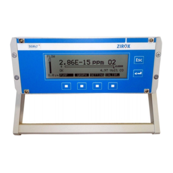
Page 24: Operation And Parametrization
8.1.1 Switch-on and measurement indication When the oxygen monitor is in operating state and all lines are connected according to chapter 7.2, the SGM5T can be switched on. The measuring cell reaches its operating temperature of 750 °C after approx. 10 minutes. -
Page 25: Status And Error Messages
Oxygen monitor SGM5T 8 Operation 8.1.4 Status and error messages During the measuring, the functions of the measuring cell are monitored. In Self-check of the SGM5T case of faults and/or error, messages are displayed. The relay output is activated simultaneously. -
Page 26: Parametrization
Oxygen monitor SGM5T 8 Operation Parametrization 8.2.1 Adjustable parameters Chart 3: Overview of the adjustable parameters Parameter Range Remark Display Displayed: In menu item “settings”-> “output 1” the measuring range for measuring (Setting via analog - Flow (vertical-bar chart) value 1 (e.g. vol%., ppm O z etc.) -
Page 27: Programming Menus
Oxygen monitor SGM5T 8 Operation 8.2.2 Programming menus The keys below the display refer to the following menus (the current meaning of the respective key is shown on the display). A definite parameter can be chosen, changed and finally confirmed with the -key. - Page 28 Oxygen monitor SGM5T 8 Operation 8.2.2.4 Output OUTPUT 1 VALUE: ppm (< 1 ppm value Option: vol%O log10, switches automatically to cell temperature, cell exponential display) voltage RANGE: 0/4-20mA 0-5 V RANGE ZERO POINT: 0 ppm Minimum: 1x10-15 ppm O...
-
Page 29: Calibration
Oxygen monitor SGM5T 8 Operation Calibration For measurements with high accuracy requirements a calibration is highly recommended (The high stability of the measuring cell requires one check- up per a year only!). The device must be in operating state for a minimum of two hours before the calibration! 8.3.1 Zero calibration... -
Page 30: Fault Clearance
Oxygen monitor SGM5T 8 Operation Fault clearance Chart 4: Disturbances, causes and clearance Disturbance Cause Clearance SGM5T off Switch on SGM5T Check current supply and Display off No current supply cord line Equipment fuse tripped Change equipment fuse Check gas supply... -
Page 31: Maintenance, Overhaul And Storage
In case of defects in measuring cell or thermocouple, send the SGM5T to the manufacturer for an overhaul. If not in use, the SGM5T has to be stored in the original packing (if possible) Storage in a dry, dust-free room. -
Page 32: Appendix
(either unheated or electrically heated), for operating in situ in various kinds of combustion installations, technical furnaces, and flames, producing the required signals. Apart from that, ZIROX produces devices with electrically heated sensors for the analysis of externally pre-mixed fuel-air compounds or of siphoned flue gases. - Page 33 Oxygen Monitor SGM5 10 Appendix For the combustion of hydrocarbon (in motor fuel, natural gas, liquid gas) with the gross formula C , the following reaction equation is obtained for λ in case of complete combustion in excess air: + λ ⋅ (n + m/4) O →...
- Page 34 Oxygen Monitor SGM5 10 Appendix Gas potentiometry using solid electrolyte sensors Crystals of mixed oxides from ZrO and CaO or Y have vacancies in the oxygen ion sublattices. Oxygen ions can migrate across them at high temperatures. Thus, they are solid electrolytes (i.e. solid ion conductors). At platinum layers on ceramic bodies of stabilized ZrO (stabilized against breaking), electrode reactions with the oxygen ion vacancies V...
- Page 35 Such isothermal cells have been realized very carefully in the ZIROX products. Unlike these, the well-known lambda probes used in automobiles with catalysts in the exhaust tube are not isothermal.
- Page 36 Oxygen Monitor SGM5 10 Appendix unburned part of the used CH vol.-% O 1100 1000 Excess Excess fuel oxygen 750 °C Fuel gas : CH λ HB_SGM5T_eng.docx...
-
Page 37: Mounting Instructions For Swagelok®-Fittings
Oxygen Monitor SGM5 10 Appendix 10.2 Mounting instructions for Swagelok®-fittings HB_SGM5T_eng.docx... -
Page 38: Activated Carbon Filter: Description And Application Notes
Oxygen Monitor SGM5 10 Appendix 10.3 Activated carbon filter: description and application notes 10.3.1 Filter construction The figure above shows the carbon filter. Two caps close a tube containing carbon. Both caps are welded into the tube. The Swagelok fittings have stoppers to keep the carbon inside. -
Page 39: Technical Data
Oxygen Monitor SGM5 10 Appendix 10.3.4 Technical data Dimensions (diameter x length) 28 mm x 150 mm Weight Approx. 285 g Volume Approx. 100 ml Duration of use Depending on the components and the concentration of the adsorbed organic components e.g. -
Page 40: Declaration Of Conformity
Oxygen Monitor SGM5 10 Appendix 10.4 Declaration of conformity HB_SGM5T_eng.docx... -
Page 41: Warranty Conditions
In case of defects and faults within 12 months (probe) and 24 months (electronics assembly) respectively after dispatch, ZIROX will clear faults at its own option by repair or replacement. The purchaser must give prompt written notice to ZIROX. -
Page 42: Your Own Notes And Remarks
Oxygen monitor SGM5T 11 Your notes 11 Your own notes and remarks HB_SGM5T_eng.docx...
Need help?
Do you have a question about the SGM5T and is the answer not in the manual?
Questions and answers