Table of Contents
Advertisement
Quick Links
Advertisement
Table of Contents

Subscribe to Our Youtube Channel
Summary of Contents for MPI TS150
- Page 1 MPI TS150 150 mm Manual Probe System User Manual...
- Page 3 Parts of this manual are subject to change without prior notice. We welcome any comments on ambiguities, errors, omissions, or missing pages. Never attempt any procedure on the MPI TS150 probe system that is not specially de- scribed in this manual. Unauthorized operation can cause faults or accidents. MPI Cor- poration is not liable for any problems resulting from unauthorized operation of the equipment.
- Page 4 You can also send e-mail to MPI Corporation using the web site.* • Other: If you purchased your MPI product from our distributors or representative, you can contact them for service and support.
-
Page 5: Table Of Contents
Accessories ............................9 Installation ����������������������������������������������������������������������� 10 Probe System Unpacking ........................10 Probe System - Transport Locks Removal ..................11 Microscope - Transport Locks Removal ....................11 TS150 Probe System Installation ......................12 Wafer Chuck Installation ........................12 Microscope Installation ........................13 System Facility Hookup ........................22 Operation ������������������������������������������������������������������������� 24 Chuck Stage ............................24... - Page 6 Mechanical Adjustments ......................42 Preventive Maintenance ......................44 General Maintenance.........................44 Troubleshooting ........................45 Service ............................46 Facility Requirements ��������������������������������������������������� 47 User Manual TS150_UG_REV 2.1.3 -20102017...
-
Page 7: Overview
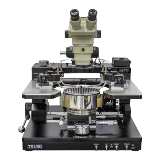
Overview MPI TS150 probe system is an effective and highly accurate manual probe system designed for precise analytical probing of substrates and 150 mm wafers. The TS150 may be configu- red to support a wide variety of on-wafer applications. TS150 Manual Probe System Front View with the Microscope... -
Page 8: Probe System Architecture
Probe System Architecture Microscope and Movement MPI TS150 microscope movement is mounted on top of the rigid microscope bridge. The bridge supports both the 25 X 25 mm Air Bearing movement and 50 mm Linear XY mo- vement with XY controlled knobs. Several microscope types are available and each has its own separate adapter. - Page 9 MicroPositioners which fit their operational familiarity thus providing immediately pro- ficiency. MPI unique MP80-DX with easy and precise definition down to 1μm - is the ideal choice for accurate and cost-effective multiline TRL – the only RF calibration method in the mmW and sub-THZ range.
-
Page 10: Non Electrical Utilities
Please connect the compressed air and vacuum supply to the system. If the probe system comes with accessories that require compressed air, nitrogen or va- cuum, connect them as necessary. One grounding point can be found at the rear base platform of the TS150 manual probe system. Electrical Utilities MPI probe system may require power supply for the system accessories. -
Page 11: Installation
Installation Prior to the shipment of TS150 probe system, please refer to the facilities preparation sheet for the space and facilities requirement for the probe system. Contact a MPI service repre- sentative for more information. Probe System Unpacking Before unpacking TS150 probe system, inspect the wooden box(es) for evidence of damage or mishandling during shipping. -
Page 12: Probe System - Transport Locks Removal
Probe System - Transport Locks Removal MPI TS150 probe system moveable stages are secured by transport locks. All transport locks are in color with secure screws. Remove all transport locks with Allen Wren- ches. Front View of TS150 with the Transport Locks. -
Page 13: Ts150 Probe System Installation
Use disposable cleanroom gloves when handling the wafer chuck to pre- vent any contamination to the chuck surface and degradation in electrical performance. Setting up the TS150 for wafer chuck installation. Adjust the Platen Lift to lift position and turn the handle knob clockwise to lock the platen lift position. -
Page 14: Microscope Installation
Microscopes: • MPI ST45 Stereo Optic with USB LED Ring Light Source • MPI SuperZoom SZ10-10x Single tube microscope with USB LED Light Source • MPI MegaZoom MZ12-15x Single tube microscope with USB LED Light Source • MPI EyeZoom EZ10-10X Binocular Microscope with USB LED Light Source. - Page 15 Step 1: Mount the microscope onto the Microscope movement� Option A: On 25 x 25 mm Air Bearing Movement� ST45, EZ10,SZ10 and MZ12 can be mounted on 25 x 25 mm Air Bearing Movement. 1. Loosen two screws mounting on the adapter of microsco- pe movement and move it backward.
- Page 16 Option C: On 50 x 50/80 x 80 ZUM/5050ZUM-VM Movement FS70 and PSM-1000 can be mounted on 5050/8080ZUM movemnent on TS150. EZ10, SZ10 and MZ12 can be mounted on 5050ZUM-VM. The installation procedures of 50 x 50/80 x 80 ZUM/5050ZUM-VM Movement are similar.
- Page 17 3. Hold the main body of PSM-1000 and align the edge of the Z lift on the left side and push to fix(see the yellow arrows on the left figure). Repeat it on right side to connect the adapter of PSM-1000 onto Z lift.
- Page 18 Step 2: �Installation of light source to microscope LED light source with remote intensity adjuster and USB power supply. Securing of LED light source to the MZ12 light source input MZ12 with thumb screw. EZ10 Install the LED Light source and fix it by fastening the thumb screw.
- Page 19 MZ12 Make sure the CCD Camera facing the front and fix two rotation points securely by a slotted screwdriver SZ10 Fix three rotation points securely with an Allen wrench. ST45 Install the C-mount adapter and hand tighten to lock the ca- mera mount.
- Page 20 Lock the CCD securely by turning the thumb screw. ST45 Mount the CCD camera and lock the rotation points. Connect the HDMI cable and the CCD power cable to the power plug. Step 4: Install Moticam 1080 digital microscope camera to the microscope C-mount�...
- Page 21 MZ12 Turn the Mocticam 1080 clockwise when mounting onto the microscope and lock the rotation points by slotted screwdriver. PSM1K Attach the adapter onto the Moticam 1080 mount. PSM1K Tighten the adapter to secure Moticam 1080. Connect the HDMI, USB Dongle and power cables. Connect the HDMI, power cable and the USB dongle of the wireless mouse.
- Page 22 1.Turn the HDMI Camera MPI 1080 clockwise onto the SZ10 microscope. 2.Fix the HDMI Camera MPI 1080 firmly onto the microscope with three points and an Allen Wrench. 3.Connect the SD card, HDMI, power cable and the USB dongle of the wireless mouse.
-
Page 23: System Facility Hookup
System Facility Hookup without Dark Box There are two built-in fittings of TS150 to be connected, including connector fitting of the wafer chuck and Vacuum and Air speed controller fittings. One optional fitting is the air fittings of the Vibration Isolation Platform. Hook up all of the facility fittings to complete the installation of the probe system. - Page 24 Installation Checklist GENERAL All transport locks have been removed All components and accessories have been installed All electrical interconnects are made and secured Non-electrical utilities are connected, including vacuum and air All components requiring AC power are plugged into outlets with the requi- red voltage and VA or wattage Check the functionality of all components Check, and adjust if necessary, the planarization of the chuck stage and...
-
Page 25: Operation
Operation The operation of the MPI TS150 probe system is divided into five different sections, to in- clude chuck stage, microscope movement, platen adjustment and control, system vacuum control, MicroPositioner Setup and Control. Chuck Stage The chuck stage has micrometer driven X, Y, and Theta fine adjustment. The puck cont- rol is used to quickly move the wafer chuck. - Page 26 Chuck Theta Fine Adjustment The theta control, located on the right side of the stage, can correct rotation of the wafer. It is generally not required when probing a single device or package, may be useful when probing multiple dies. Standard theta travel can be replaced by fine tra- vel movement of ±5°.
-
Page 27: Microscope Movement
Microscope Movement MPI TS150 probe system can be configured with six microscopes and six movements. Microscopes: • MPI ST45 Stereo Optic with USB LED Ring Light Source • MPI SuperZoom SZ10-10x Single tube microscope with USB LED Light Source •... - Page 28 PSM1000 FS70 EZ10 Height Adjustment SZ10 and MZ12Microscope Turn the coarse adjustment knob and move the main body of the microscope to either an upper or lower position to obtain the image coarsely. Turn the fine adjust- ment knob and move the main body of the microscope to either an upper or lower position to obtain the sharpest image.
- Page 29 Fine Height Adjustment ST45 Microscope Turn the Height Adjustment knob clockwise to move down the height of the microscope; to turn the Height Adjustment knob counterclockwise to move up the height of the microscope PSM1000/FS70 Microscope Pull and turn the height adjustment control knob to move up and down the microscope.
- Page 30 XYZ Movement Adjustment Operate XY Stage movemnet of 25 X 25 mm air bearing controlled knob Pull the air-bearing controlled knob to the right or left to move the X movement of the microscope and pull it forward to quickly move the microscope to the center of the chuck and push it back to relocate the microscope.
- Page 31 Operate Z stage of 5050/8080 ZUM Microscope Movement The Z movement includes pneumatic Z up movement and manual Z up movement. Pneumatic Z Up Movement: Turn on the switch to automatically raise the Z movement of the microscope to 80 mm or plus. Turn the switch off to lower the Z movement au- tomatically.
- Page 32 Operate 50 x 50 mm ZUM-VM Microscope Movement The XY Movement of 5050ZUM-VM is the same as 50 X 50 mm Linear Movements. Plea- se refer to the operation of 50 X 50 mm Linear Movements. Pneumatic Z Up Movement: Turn on the switch of SCOPE to automatically raise the Z movement of the microscope to 140 mm or plus.
- Page 33 Focus Adjustment Turn the coarse or fine height adjustment knob until the DUT is clear in the LCD monitor. On ST45 Turn the coarse height adjustment knob until the DUT is clear in the LCD Monitor or from the eyepiece. ST45 provides two ways to view the probing.
- Page 34 Operation of EZ10 1. Turn on the LED lighting and adjust to the maximum light intensity. 2. While watching the eyepieces the eyepieces of trinocular head and slide the interpu- pillary by hands so that the right and left visual fields should be one. Interpupillary distance has individual differences.
-
Page 35: Platen Adjustment And Control
Platen Adjustment and Control The platen controls (except the platen cable clamps) are valid only for the manual drive pla- ten. The platen controls include the coarse platen height adjustment control lever, the preci- se contact/separation/safety load, and the platen safety load lock by the platen lift. Contact /Separation/Safety Load of the Platen Lift The unique platen lift provides three discrete positions for contact, separation up to 300 μm and safety loading up to 3... -
Page 36: System Vacuum Control
System Vacuum Control Four vacuum ON/OFF switches located on the front-bottom panel of TS150 from right to left are Chuck, Aux Right, Left and Scope. Switch on chuck vacuum control when operating the wafer chuck and vice versa. Switch on Right and Left Auxiliary to controls vacuum for the ca- libration substrates of the Right and Left auxiliary chucks. -
Page 37: Micropositioner Setup And Control
MicroPositioner Setup and Control All MPI MicroPositioners have magnetic base to create the extreme stable force when mounting the platen. Switch “ON” to mount it firmly onto the platen and switch “OFF” to remove it from the platen. XYZ Stage Movement Adjustment Turn the X stage movement control knob clockwise to move the X stage to the left;... - Page 38 Mount DC Arm and Probe Tip 1.Bolt the universal DC adapter onto the MicroPositioner with an Allen Wrench and two screws provided. Two blue lines on the figure below are the screw locations of each MicroPositioner. MP60 MP50 MP40 MP25 2.Mount the probe arm and then turn the thumb screw of the universal DC adapter clockwise to fix the probe arm.
- Page 39 Mount Kelvin Arm and Probe Tip on Open Probe System 1. Mount the Kelvin probe tip and fix it with two screws on the Kelvin arm and with a slot- ted screwdriver. 2. Mount the probe arm and then turn the thumb screw of the universal DC adapter clock- wise to fix the probe arm Kelvin on the height indicator.
- Page 40 Mount RF Probe Arm/Probe with MicroPositioner 1.Remove the two screws on the probe platen and bolt them to the guide for rectangular adjustment provided in the package of RF Probe Arm on the probe platen by Allen Wrench. To easily operate the MicroPositioner, align it with the guide for rectangular adjustment, move it forward and backward when installing RF Probe and probing.
- Page 41 3.One screw supplied to bolt the cable clamp(screwed location depends on the Left or Right version of the MicroPositioner you purchased). 4.Bolt the RF probe arm adapter onto the MicroPositioner by Bolt RF Probe Arm Adap- using an Allen Wrench. Slide the RF probe arm to the MicroPo- sitioner to complete the assembly.
- Page 42 6.Turn the thumb screw counterclockwise to move the RF Probe arm downward and then lock the RF Probe arm by the thumb screw. The height adjustment of the RF Probe arm is ± 5 mm. The fine micrometer screw is used for RF Probe planarity adjustment.
-
Page 43: Maintenance And Service
These adjustment procedures ensure system accuracy and reliability. Wafer Chuck Planarization Procedure NOTE Wafer chuck planarization should be performed by a MPI service repre- sentative. Wafer chuck planarization ensures equal probe contact force from tip-to-tip of probes and throughout the wafer chuck range of travel. The wafer chuck is planarized at the fac- tory, but adjustment may be required at installation. - Page 44 Levelling Screw Levelling Screw Levelling Screw Set Screw Set Screw 2. The adjustment of the wafer chuck planarization is up to 10 μm. Higher than 10 μm, wafer chuck planarization procedure has to be executed. Use Allen Wrench to tighten or loosen the screw.
-
Page 45: Preventive Maintenance
Preventive Maintenance The TS150 requires minimal preventive maintenance. Take care to keep the system clean and covered when not in use. The following cleaning and lubrication procedures should be performed at the recommended intervals. -
Page 46: Troubleshooting
Visual Checks Perform a thorough visual check of the system before each use. Key areas include the wafer chuck assembly, X/Y stage, platen separation, microscope movement assem- bly, individual MicroPositioner, Frequency Extender and the microscope. These parts should be free of dust, residue, and rust. Instrument Operation A typical examination of components should include the Z stroke movement, the pla- ten separate/contact/safety load mechanism, and the MicroPositioners as well as the... -
Page 47: Service
Repacking To retain the validity of the warranty, always use the original packing materials. Cont- act a MPI representative for replacement shipping materials or hardware. Remove all probes and accessories from the probe system, including the microscope. Do not ship them unless they are associated with the failure symptoms. -
Page 48: Facility Requirements
Facility Requirements Requirements Description • Flow rate insignificant Vacuum • -0.5 bar (for single DUT) / -0.3 bar (for wafers) • Include 6 mm hose and 6 mm wall fitting Air and vacuum Compressed air for • Filtered, dry and oil-free Vibration Isolation •... - Page 49 470 x 505 x 635 mm (18.5 x 19.9 x 25 in) Weight ~60 kg (132 lb.) Top View Front View Vibration Isolation Platform VIP TS150 530 x 630 x 60 mm Dimensions (W x D x H) (20.9x 24.8 x 2.4 in) Weight Approx. 30 kg ( 66 lb.) User Manual TS150_UG_REV 2.1.3 -20102017...
Need help?
Do you have a question about the TS150 and is the answer not in the manual?
Questions and answers