Table of Contents
Advertisement
Quick Links
Advertisement
Table of Contents

Related Manuals for NTM BG7

Summary of Contents for NTM BG7
-
Page 2: Table Of Contents
TABLE OF CONTENTS CHAPTER 1……..SPECIFICATIONS ..................1 CHAPTER 2…..PRECAUTIONS ....................2 CHAPTER 3………. GENERAL MAINTENANCE .................3 Recommended Lubricants and Fluids ............4 CHAPTER 4………. ELECTRICAL CONTROLS AND OPERATION ..........5 CHAPTER 5………. REEL STANDS, REELS AND EXPANDABLE ARBORS ......11 CHAPTER 6………. HYDRAULIC SYSTEMS ................16 Maintenance ...................16 Hydraulic Fluid Troubleshooting ............16 CHAPTER 7………. - Page 3 LIST OF FIGURES Figure 1: Controls ..........................8 Figure 2: Main Control Cable ......................9 Figure 3: Main Control Box Fuse ..................... 10 Figure 4: QCPP E 1-6 Fuse Location ....................10 Figure 5: Expandable Arbor Set-Up ....................12 Figure 6: Expandable Reel Assembly ....................14 Figure 7: Hydraulic System –...
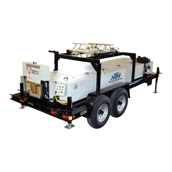
- Page 4 CHAPTER 1 BG7 SPECIFICATIONS SPECIFICATIONS BG7 Dimensions: Length-14’ 6” (4.4m) Width-4’ (1.7m) Height-4’ 3” (1.3m) w/Over Head Rack 2’ 8” (.8m) w/o Over Head Rack Weight-1800 lbs. (820kg) SSQ on Trailer: Length-21’ (7.7m) Width-7’ (2.1m) Height-6’ 3” (1.9m) with reel Weight-4560 lbs.
- Page 5 CHAPTER 2 PRECAUTIONS PRECAUTIONS Make sure the operator of the machine has read and understands this manual in its entirety before attempting to operate this equipment. ALWAYS keep covers, guards and lids mounted to machine during operation OBSERVE and OBEY all safety and warning signs affixed to the machine. ALWAYS adhere to and follow all local and national safety codes concerning the loading and un-loading of reeled coils.
- Page 6 CHAPTER 3 GENERAL MAINTENANCE GENERAL MAINTENANCE 1. Always keep covers on during operation and storage. The covers are for operator safety, but also protect the internal components of the machine from the environment. 2. Avoid storage of the machine outdoors for long periods of time. Cover your machine with a tarp to protect it but provide good ventilation to prevent condensation and rust.
-
Page 7: Recommended Lubricants And Fluids
NTM PN: LUBE-GREASE - 14 Ounce Container Open Gear Spray Lubricant for: Main Drive Gears Open Gear and Wire Rope Lubricant NTM PN: LUBE-GEAR - 11 oz. Aerosol Can Hydraulic Fluid (32AW) for: Hydraulic Tank NTM PN: HYD-200-018 - 5 Gallons... - Page 8 CHAPTER 4 ELECTRICAL CONTROLS AND OPERATION ELECTRICAL CONTROLS AND OPERATION POWER CORD REQUIREMENTS For machines equipped with a QCPP-E it is very important to follow the power cord requirement prescribed by the motor and electrical control manufacturers to maintain their respective warranties.
- Page 9 CHAPTER 4 ELECTRICAL CONTROLS AND OPERATION Function #1 (Power On) Pull this button OUT prior to starting the machine. Function #2 (Emergency Stop-Power Off) Once the machine is running, pushing this button in will stop all functions and completely shut down the machine including the engine. If the shear is in the down cycle it will freeze it in position.
- Page 10 CHAPTER 4 ELECTRICAL CONTROLS AND OPERATION FUSES (Figure 3) All machines, gas or electric powered, have a 10-amp time delay fuse inside the Electrical Control Panel Assembly. This fuse protects the electrical components. If the fuse is blown, you will lose all functions of the machine except Motor Start. To replace this fuse: Loosen all 4 cover screws and open the front panel of the Control Box.
-
Page 11: Figure 1: Controls
CHAPTER 4 ELECTRICAL CONTROLS AND OPERATION Figure 1: Controls... -
Page 12: Figure 2: Main Control Cable
CHAPTER 4 ELECTRICAL CONTROLS AND OPERATION Figure 2: Main Control Cable... -
Page 13: Figure 3: Main Control Box Fuse
CHAPTER 4 ELECTRICAL CONTROLS AND OPERATION Figure 3: Main Control Box Fuse Figure 4: QCPP E 1-6 Fuse Location... - Page 14 CHAPTER 5 REEL STANDS, REELS, AND EXPANABLE ARBORS REEL STANDS, REELS AND EXPANDABLE ARBORS EXPANDABLE ARBOR (Figure 5) The Expandable Arbor adjusts to accommodate coils with 16” to 20” inside diameters by expanding into the ID of the coil. THREADED NUT The threaded nut should always be on the right side of the machine and the tail of the coil should always be routed over the top and pointing toward the exit or shear end of the machine.
-
Page 15: Figure 5: Expandable Arbor Set-Up
CHAPTER 5 REEL STANDS, REELS, AND EXPANABLE ARBORS Figure 5: Expandable Arbor Set-Up... - Page 16 CHAPTER 5 REEL STANDS, REELS, AND EXPANABLE ARBORS CAUTION: Always use properly rated lifting devices to load and unload coils. Maximum Capacity / Reel: 3,000 lbs. Total Capacity for Reel Stand: 6,000 lbs. 1. The reel shafts must rest in the cradles on the reel rack. Keep the cradles lubricated with synthetic lube to minimize wear.
-
Page 17: Figure 6: Expandable Reel Assembly
CHAPTER 5 REEL STANDS, REELS, AND EXPANABLE ARBORS Figure 6: Expandable Reel Assembly... - Page 18 CHAPTER 5 REEL STANDS, REELS, AND EXPANABLE ARBORS LOADING REELED COIL Caution: Always use a forklift or other approved lifting device to load or unload Fixed Reels or Expandable Arbors loaded with coil. The Lifting Holes in the Fixed Reel sides are provided to make loading safer and easier. DO NOT use lifting straps through the lifting holes as the sharp edges may cut the straps.
-
Page 19: Maintenance
CHAPTER 6 HYDRAULIC SYSTEMS HYDRAULIC SYSTEMS Maintenance (Figure 7) The hydraulic system for your machine is a very durable and reliable system. It must be properly maintained to ensure trouble free operation and longevity. The factory has installed a 32 weight AW hydraulic fluid. -
Page 20: Figure 7: Hydraulic System - Overview
CHAPTER 6 HYDRAULIC SYSTEMS Figure 7: Hydraulic System – Overview... -
Page 21: Figure 8: Hydraulic System - Details
CHAPTER 6 HYDRAULIC SYSTEMS Figure 8: Hydraulic System – Details Figure 9: Hydraulic Fluid Level... -
Page 22: Figure 10: Tightening The Chain
CHAPTER 7 DRIVE SYSTEM DRIVE SYSTEM The drive rollers are set at the factory and should not need adjustment. Over time, the chains will wear down causing them to get longer and the chain tensioning sprockets will need to be adjusted to keep the chain tight. -
Page 23: Figure 11: Shear Height Adjustment
CHAPTER 8 SHEAR ASSEMBLY SHEAR ASSEMBLY OPERATION Push the SHEAR DOWN button to activate the shear cycle and cut material. IN CASE OF AN EMERGENCY: Push the SHEAR UP button during the down cycle to immediately send the shear up to the home position. The shear is electrically activated and hydraulically driven. -
Page 24: Figure 12: Shear Left-Right Adjustment And Removal
CHAPTER 8 SHEAR ASSEMBLY Adjusting the left-right position of the shear: 1. Shut off power to the machine 2. Remove the shear cover, then loosen the six “A” bolts but do not remove. 3. Use a large screwdriver to pry on the slots (Figure 12) until the shear is located correctly. 4. - Page 25 Proper lubrication is essential to clean cuts, rust prevention and longevity. Spray Lube for: Shear Blades, Dies, Entry Guide, Bead Roller Carriage Shafts, Acme Shafts and Mitre Gears Super Lube - Multi-Purpose Synthetic Aerosol Lubricant with Syncolon (PTFE) NTM PN: LUBE-SPRAY - 11oz can...
-
Page 26: Figure 13: Entry Guide Adjustment
CHAPTER 9 ENTRY GUIDE & DRUM ASSEMBLY ENTRY GUIDE AND DRUM ASSEMBLY ENTRY GUIDE ADJUSTMENT Figure 13: Entry Guide Adjustment ENTRY DRUM ADJUSTMENT Figure 14: Entry Drum Adjustment... -
Page 27: Figure 15: Run Out Table
CHAPTER 10 RUN OUT TABLES RUN OUT TABLES (Figure 15) The Run-Out Table attaches to the Exit End of the Shear assembly, and is used to support the gutter as it exits the machine. It is available in 10 ft. long sections that fasten together, and have adjustable legs so they can be set to the correct height. -
Page 28: Figure 16: Post Face Knife Roller Adjustment
CHAPTER 11 POST-FACE KNIFE ROLLER ADJUSTMENT POST-FACE KNIFE ROLLER (Figure 16) When changing the coil from steel to aluminum, or vice-versa, the post-face knife roller needs to be adjusted in order to maintain a quality gutter. To do this, follow the procedure below. -
Page 29: Figure 17: Pressure Switch Adjustment
CHAPTER 12 TROUBLESHOOTING TROUBLESHOOTING The hydraulic system operates the Shear and Drive assemblies. They are interfaced together and electronically activated. The hydraulic system pressure is factory set at 2000 psi and should not be changed. Some of the common problems that occur and their solutions follow below. - Page 30 CHAPTER 12 TROUBLESHOOTING 2. Shear travels to the bottom of the stroke and returns to the top of the stroke without cutting the panel completely through. SOLUTION: Press and hold the Green Shear Down Button until the panel is cut off.
-
Page 31: Figure 18: Limit Switch Adjustment
CHAPTER 12 TROUBLESHOOTING Figure 18: Limit Switch Adjustment 4. Manual Control Panel buttons do not work. SOLUTION #1: Check fuse inside of Manual Control Box. Replace if blown with a 10-amp time delay fuse (Figure 3 on page 10). SOLUTION #2: If you have a gasoline engine, check the condition of the battery. The control system requires 12 volts to operate properly. -
Page 32: Engaging Or Disengaging The Hook
CHAPTER 13 HOOK ASSEMBLY (OPTIONAL) HOOK ASSEMBLY (OPTIONAL) (Figure 19) The Hook Assembly is a self-contained assembly which can be added to a gutter machine. The New Tech machine is capable of running a straight back (with a bead) or hook type gutter profile from the same machine. -
Page 33: Figure 20: Bead Roller Adjustment
CHAPTER 13 HOOK ASSEMBLY (OPTIONAL) Figure 20: Bead Roller Adjustment... -
Page 34: Figure 21: Plc Assembly
APPENDIX A PLC CONTROLLER PLC CONTROLLER Figure 21: PLC Assembly Figure 22: Serial Number Plate A - 1... -
Page 35: Home
APPENDIX A PLC CONTROLLER Home When the controller is turned on, it will automatically go to the home screen. Figure 23: Home Screen Manual Operation The machine can be manually operated from the home screen by pressing the Jog and Shear buttons. -
Page 36: Job Entry
APPENDIX A PLC CONTROLLER Pre-Run Sequence: Jog the material forward using the manual FWD JOG or MICRO buttons on the Home screen or the JOG switch at the entry end of the machine. The material must exit the shear and be detected by the panel detection sensor. -
Page 37: Clear Jobs
APPENDIX A PLC CONTROLLER programmed after the current job, the controller will stop and return to the Job Entry screen. Clear Jobs To clear the current job on the screen press Clear Job. To clear all the jobs in the controller, press Clear All. -
Page 38: Automatic Operation
APPENDIX A PLC CONTROLLER Automatic Operation In the Auto Run screen, the current job and progress are displayed. Press the Start button to begin running the job. When the current job is complete the next job will start if the No button for pause was pressed for the current job. -
Page 39: Setup
APPENDIX A PLC CONTROLLER Figure 28: Calibration Screen The controller will display the theoretical length of the part after it is produced. The theoretical length may be slightly different than the intended calibration length due. Measure the length of the part and input the length in the Actual Measured Length fields. Press Enter to re-calibrate the controller or Cancel to return to the Home screen without making any changes to the controller. -
Page 40: Status/Diagnostics
APPENDIX A PLC CONTROLLER Figure 30: Setup Screen In the Setup screen, the Units of Measure can be changed to Imperial units in either feet and inches (ft/in) or only inches (in) or Metric units (mm). Example: ft/in: 10’ 4 1/16” 124 1/16”... -
Page 41: Security
APPENDIX A PLC CONTROLLER The Status 1 screen shows the condition of the Hydraulic Pressure Switch and the Top of Stroke Limit Switch. If one or both of the TOS Shear Limit Switches are not activated the TOS Shear Limit Switch light will be on. Refer to the Shear section in the machine manual for limit switch adjustment. -
Page 42: Coil Tracking
APPENDIX A PLC CONTROLLER Coil Tracking: From the Home screen, press the Coils button to change the coil of material to track. If the security is turned on, a password must be entered if changes to the stored coils are necessary. -
Page 43: Colors
APPENDIX A PLC CONTROLLER Example: The controller is set to run a black coil designated as Coil #2 and the user changes to a white coil designated by Coil #1. From the Home screen, press the Coils button which will bring up the Coil #2 information. -
Page 44: Coil Length Calculator
APPENDIX A PLC CONTROLLER Figure 36: Coils Color Screen Coil Length Calculator The controller has a built in calculator to estimate the length of a coil based on the dimensions of the coil. From the Coils screen, press Length Calculator button. Figure 37: Length Calculator Screen Press the Select Material button to select the thickness and type of material. -
Page 45: Figure 38: Material And Thickness Screen
APPENDIX A PLC CONTROLLER Figure 38: Material and Thickness Screen Then enter in the Inside Diameter of the Coil, Width of the coil and thickness of the coil. The thickness of the coil is the difference between the Inside Diameter (ID) and the Outside Diameter (OD). - Page 46 ELECTRICAL SCHEMATICS Sheet Drawing Number Number Description PLC-380-000 Electrical Assembly – Parts List PLC-380-000 Electrical Assembly – Wiring Details PLC-381-000 Control Box Assembly – Parts List PLC-381-000 Control Box Assembly – Outside & Inside Views PLC-381-000 Control Box Assembly – Wiring Schematic PLC-381-000 Control Box Assembly –...
- Page 47 Parts List ITEM PART NUMBER TITLE ELC-100-015 CABLE, 5 PIN, MALE X 6M ELC-400-101 CABLE, 6 PIN, MALE/FEMALE X 4M ELC-400-105 CABLE, 4 PIN, MALE X 2M ELC-400-106 CABLE, 3 PIN, MALE X 2M FAS-HC5-118 HEX HEAD CAP SCREW, 1/4-20 x 1" LG. INSTALL GROMMET FAS-HC5-278 HEX HEAD CAP SCREW, 1/4-20 x 2"...
- Page 48 MAIN CONTROL BOX REV FOR START SHEAR FEED N.O. DOWN STOP N.O. N.O. COMPONENTS N.C. N.C. SHEAR N.O. PANEL LENGTH N.C. N.O. N.C. STOP N.C. MOTOR JOG-RUN FEED START N.C. N.O. N.O. SHEAR MOTOR DOWN ENTRY END/REMOTE CONTROL REMOTE N.O. REMOTE STOP TOS-LEFT...
- Page 49 PARTS LIST ITEM PART NUMBER TITLE DCL-100-017 DECAL, ASSEMBLED IN MEXICO ELC-100-017 FEMALE CLOSURE CAP ELC-100-018 MALE CLOSURE CAP ELC-100-021 ENCLOSURE ELC-110-000 TERMINAL BLOCK/RELAY ASSEMBLY ELC-300-103 PUSH BUTTON, GREEN ELC-300-104 SELECTOR SWITCH, W/1 N.O. ELC-300-107 PUSH BUTTON, RAISED RED ELC-300-109 SELECTOR SWITCH, 2 POS,1 N.O.
- Page 50 MEXICO ONLY 4X DRILL HOLES TO 1/4" EARTH GROUND POINT LABEL "REV 5" ON INSIDE OF BOX SECTION B-B LENGTH: 42" FROM STRAIN RELIEF NEW TECH MACHINERY MATERIAL LENGTH FINISH CORP. SEE BOM TOLERANCES DRAWN BY PART NAME ECR NO. DATE RELEASED BY .XX =...
- Page 51 N.O. FWD/REV JOG/RUN START FEED REMOTE N.O. COMM N.O. N.C. STOP N.C. N.C. N.O. N.C. N.O. N.O. N.O. -NEG SHEAR +POS UP - DOWN -NEG +POS N.O. +12V TOS LS N.C. SHEAR UP SHEAR DOWN STOP FEED LEFT N.C. N.O. N.C.
- Page 52 E-STOP FROM QCPP +12V LINE 1000 +12V TO LINE 1006 N.C. 1001 LEGEND QCPP 1002 GROUND TERMINAL BLOCK PIN NUMBER PANEL QCPP 1003 LENGTH GAS KILL GRN/YEL FUSE GROUND N.O. CONTACT (N.O.) 1004 CONTACT (N.C.) GRN/YEL LOCATE GRD TOP LEFT OF BOX MUSHROONM HEAD FROM QCPP 1005...
- Page 53 FROM LINE 1019 FROM LINE 1019 JUMPER INSIDE LEFT T.O.S. +12V -12V LINE 1020 SHEAR T.O.S. LEFT 1021 N.C. N.C. T.O.S. PLC OUT (SHEAR UP) LEGEND RIGHT 1022 TERMINAL BLOCK N.C. PIN NUMBER 1023 FUSE SHEAR SHEAR DOWN CONTACT (N.O.) +12V 1024 CONTACT (N.C.)
- Page 54 CONTROL RELAYS 106 103 114 118 OUT IN +12v COMPONENTS ENTRY END/REMOTE CONTROL PANEL LENGTH REMOTE N.O. N.C. N.O. SHEAR MOTOR DOWN REMOTE STOP N.C. TOS-LEFT TOS-RIGHT N.O. N.O. 70 10 +12v N.C. N.C. 13 410 HYDRO ON N.O. N.O. +12v N.O.
- Page 55 1 6 2 6 5 E . 3 3 r d D r . S t e 4 0 | A u r o r a , C O 8 0 0 1 1...
Need help?
Do you have a question about the BG7 and is the answer not in the manual?
Questions and answers