Table of Contents
Advertisement
Advertisement
Table of Contents

Summary of Contents for Raisecom iTN8600-I
- Page 1 (A) Product Description (Rel_01)
- Page 2 Website: http://www.raisecom.com Tel: 8610-82883305 Fax: 8610-82883056 Email: export@raisecom.com Address: Raisecom Building, No. 11, East Area, No. 10 Block, East Xibeiwang Road, Haidian District, Beijing, P.R.China Postal code: 100094 ----------------------------------------------------------------------------------------------------------------------------------------- Notice Copyright © 2019 Raisecom All rights reserved.
- Page 3 (A) Product Description Preface Preface Objectives This document describes the iTN8600-I in terms of overview, system structure, product features, and technical specifications. The appendix lists compliance standards and protocols, terms, acronyms, abbreviations involved in this document. Versions The following table lists the product versions related to this document.
- Page 4 Heading 1, Heading 2, Heading 3, and Block are in Book Antiqua. Change history Updates between document versions are cumulative. Therefore, the latest document version contains all updates made to previous versions. Issue 01 (2019-12-01) Initial commercial release Raisecom Proprietary and Confidential Copyright © Raisecom Technology Co., Ltd.
-
Page 5: Table Of Contents
3.3 AC power supply RPA1171-220S12 ......................20 3.3.1 Version ..............................20 3.3.2 Appearance ............................20 3.3.3 Functions ............................... 21 3.3.4 Interface ..............................21 3.3.5 LED ............................... 21 3.3.6 Technical specifications ........................22 3.3.7 Cable ..............................22 Raisecom Proprietary and Confidential Copyright © Raisecom Technology Co., Ltd. - Page 6 5.2.3 Configuration cable ..........................47 5.2.4 Power cables ............................48 5.2.5 Ground cable ............................52 5.3 Compliant standards and protocols ........................ 54 5.4 Terms ................................55 5.5 Acronyms and Abbreviations ......................... 57 Raisecom Proprietary and Confidential Copyright © Raisecom Technology Co., Ltd.
- Page 7 Figure 1-1 Front appearance of the iTN8600-I-XT4D-AC ..................2 Figure 1-2 Front appearance of the iTN8600-I-XT4D-DC ..................2 Figure 1-3 Appearance of the iTN8600-I-XT4D-AC and iTN8600-I-XT4D-DC ..........2 Figure 1-4 Typical point-to-point application ......................4 Figure 1-5 Typical point-to-point WDM application ..................... 5 Figure 1-6 Typical ring network application ......................
- Page 8 Table 3-16 AC power cable ..........................22 Table 3-17 Version of the fan ..........................22 Table 3-18 Functions of the fan ..........................23 Table 3-19 Default configurations of the iTN8600-I-XT4D ................23 Table 4-1 Overall specifications ........................... 24 Table 4-2 Reliability indexes ..........................25 Raisecom Proprietary and Confidential Copyright ©...
- Page 9 Table 5-14 Wiring of the fiber ..........................44 Table 5-15 Wiring of EIA/TIA 568 A and EIA/TIA 568 B standards ..............45 Table 5-16 Technical specifications of the Raisecom straight-through cable ............47 Table 5-17 Technical specifications of the configuration cable ................48 Table 5-18 Technical specifications of the DC power cable.................
- Page 10 Raisecom iTN8600-I (A) Product Description Tables Raisecom Proprietary and Confidential viii Copyright © Raisecom Technology Co., Ltd.
-
Page 11: Overview
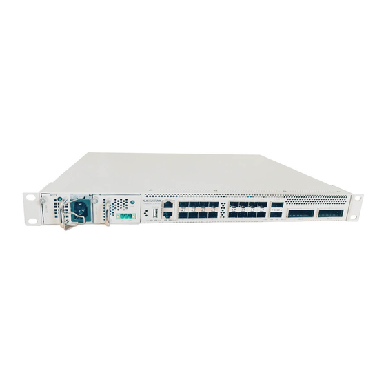
The iTN8600-I adopts a standard 19-inch wide and 1U high chassis. It can be installed in the standard cabinet with depth of 600 mm and width of 19-inch, or on a workbench. The compact design not only makes the device highly integrated but also reduces the overall space. -
Page 12: Networking Application
Figure 1-3 Appearance of the iTN8600-I-XT4D-AC and iTN8600-I-XT4D-DC 1.2 Networking application The iTN8600-I, oriented to the OTN access network, supports accessing services of 10 Gbit/s to 100 Gbit/s. It can network with OTN aggregation devices to implement service access, integration, and multiplexing at the network edge and transmit multi-point services uniformly with large granularities, thus effectively saving fiber resources on the network. - Page 13 Typical point-to-point application As shown in Figure 1-4, the iTN8600-I, as the access OTN device, can be directly connected to the iTN8600 or the client device with services of multiple rates, and access and carry services with high bandwidth.
-
Page 14: Figure 1-4 Typical Point-To-Point Application
Dual fibers Typical point-to-point WDM application As shown in Figure 1-5, based on point-to-point application, the iTN8600-I is connected downstream to the WDM network, so it supports higher bandwidth, 10/100 Gbit/s hybrid transmission, and smooth upgrade. Raisecom Proprietary and Confidential... -
Page 15: Figure 1-5 Typical Point-To-Point Wdm Application
Dual fibers Typical ring network application As shown in Figure 1-6, line-side interfaces on the iTN8600-I support forming a ring network. The client-side interface supports transmitting multiple types of services upstream and downstream and form the ring network service route of two directions through ODUk SNCP 1+1 protection. -
Page 16: Ordering Information
The line side supports OCh 1+1 protection and ODUk SNCP 1+1 protection. When the iTN8600-I-XT4D accesses OTU2/OTU4 services at the client side, it supports OCh 1+1 protection and ODUk SNCP 1+1 protection. When it accesses other services, it supports interface protection. -
Page 17: Table 1-2 Client-Side Service Modes
Two power supplies support automatic 1+1 hot backup. They must be connected to different power sourcing equipment or lines to prevent the iTN8600-I from being powered off due to power failure of one power sourcing equipment or line. ... -
Page 18: Purchased Parts
FANS383 Power supply black Power supply black panel, with the ordering model of panel/RoHS RC8.041.1349 Rack mount Bracket used for the 19-inch cabinet, with the ordering model of kit/RoHS RC8.043.169 Raisecom Proprietary and Confidential Copyright © Raisecom Technology Co., Ltd. -
Page 19: Table 1-4 Ordering Information About Purchased Cables
Keep correct direction of cooling air flow inside the chassis. Cables The configuration cable and power cable are delivered with the iTN8600-I, and they can be additionally purchased. The power cable depends on the actual situation of the target area. When you order the iTN8600-I, specify one power cable. -
Page 20: Table 1-5 Comparison Table For Services, Quantity, Panel Interfaces, And Optical Modules
Commercial dual-fiber 10 km: UQP-100G/LR4 Commercial dual-fiber 30 km: UQP-100G/ER4L Services: client-side OTU4 Quantity: up to 2 ways Commercial dual-fiber 10 km: UQP-100G/LR4 Panel interfaces: C17–C18 Raisecom Proprietary and Confidential Copyright © Raisecom Technology Co., Ltd. - Page 21 Services: line-side OTU4 Commercial dual-fiber 10 km: UC2-100G/LR4 services Commercial dual-fiber 40 km: UC2-100G/ER4 Quantity: up to 2 ways Commercial dual-fiber 2400 km: UC2-100G/DCO Panel interfaces: L1–L2 Raisecom Proprietary and Confidential Copyright © Raisecom Technology Co., Ltd.
-
Page 22: System Structure
Software structure 2.1 Hardware structure The iTN8600-I is composed of the chassis (including the backplane), power supply, fan, and MCC. Figure 2-1 shows the hardware structure of the iTN8600-I-XT4D. All modules are located on the front panel and rear panel. The two sides of the chassis are closed surface. Two ground... -
Page 23: Software Structure
(A) Product Description 2 System structure 2.2 Software structure Based on the Operating System (OS) and hardware drive, the iTN8600-I supports multiple services and functions, and the NView NNM system. Figure 2-2 shows the software structure of the iTN8600-I. -
Page 24: Cards And Parts
Raisecom iTN8600-I (A) Product Description 3 Cards and parts Cards and parts This chapter describes MCCs of the iTN8600-I, including the following sections: iTN8600-I-XT4D DC power supply RPD1304-48S12 AC power supply RPA1171-220S12 Fan FANS383 Default configurations 3.1 iTN8600-I-XT4D... -
Page 25: Functions
Table 3-2 lists functions of iTN8600-I. Table 3-2 Functions of iTN8600-I Function Description The iTN8600-I-XT4D supports OTN Muxponder, Transponder, and Basic functions ADM applications. The line side supports the CFP2 optical module to transmit 2 ways of 100 Gbit/s OTU4 services at the line side. - Page 26 The line side supports OCh 1+1 protection and ODUk SNCP 1+1 Protection protection. By default, no protection is configured. When the client-side interface accesses OTU2 services, it supports OCh 1+1 protection and ODUk SNCP 1+1 protection. When it Raisecom Proprietary and Confidential Copyright © Raisecom Technology Co., Ltd.
-
Page 27: Interfaces
Support configuring relevant optical modules. Support hot swapping. Upgrade Support upgrading system software online. 3.1.4 Interfaces Table 3-3 lists interfaces on the iTN8600-I. Table 3-3 Interfaces on the iTN8600-I Print Type Description Debugging serial interface, connected to the... -
Page 28: Leds
Raisecom iTN8600-I (A) Product Description 3 Cards and parts 3.1.5 LEDs Table 3-4 lists LEDs on the iTN8600-I. Table 3-4 LEDs on the iTN8600-I Print Color Description Green System working LED Green: the system works abnormally. Off: the system works abnormally. -
Page 29: Functions
3.2.5 LED Table 3-8 LED on the DC power supply Print Color Description Green Power LED Green: the power supply is normal. Off: the power supply is abnormal. Raisecom Proprietary and Confidential Copyright © Raisecom Technology Co., Ltd. -
Page 30: Technical Specifications
A.00 or later 3.3.2 Appearance Figure 3-3 shows the panel of the AC power supply, including the captive screw, heat dissipation holes, handle, power LED, power interface, and power cable clip. Raisecom Proprietary and Confidential Copyright © Raisecom Technology Co., Ltd. -
Page 31: Functions
3.3.5 LED Table 3-14 LED on the AC power supply Print Color Description – Green Power LED Green: the power supply is normal. Off: the power supply is abnormal. Raisecom Proprietary and Confidential Copyright © Raisecom Technology Co., Ltd. -
Page 32: Technical Specifications
3.4.1 Version Table 3-17 Version of the fan Model Version FANS383 A.00 or later 3.4.2 Appearance Figure 3-4 shows the appearance of the fan, including the captive screw and handle. Raisecom Proprietary and Confidential Copyright © Raisecom Technology Co., Ltd. -
Page 33: Functions
Support fan fault alarms, including the alarm of decrease of the rotational speed due to fan stopping rotating and fan aging. 3.5 Default configurations Table 3-19 lists default configurations of the iTN8600-I-XT4D. Table 3-19 Default configurations of the iTN8600-I-XT4D Type Default configuration ... -
Page 34: Technical Specifications
Raisecom iTN8600-I (A) Product Description 4 Technical specifications Technical specifications This chapter describes technical specifications of the iTN8600-I, including the following sections: Overall specifications Laser safety class Reliability specifications EMC specifications Security standards Environmental requirements 4.1 Overall specifications... -
Page 35: Laser Safety Class
1° C. 4.2 Laser safety class According to the laser Tx optical power, the laser safety class used by the iTN8600-I is Class When the safety class of laser used by the iTN8600-I is Class 1, the maximum Tx optical power of the optical interface is smaller than 10 dBm (10 mW). -
Page 36: Emc Specifications
Temperature (° C) (altitude: 0–1800 m) -45 to +70 Relative humidity (indoor) 10%–90% ≤ 1120 Solar radiation (W/m² ) ≤ 600 Heat radiation (W/m² ) ≤ 20 Wind speed (m/s) Raisecom Proprietary and Confidential Copyright © Raisecom Technology Co., Ltd. -
Page 37: Table 4-4 Concentration Requirements For The Mechanical Active Substance In Storage
Generally, the iTN8600-I should be installed indoor. Ensure that there is no impounded water on the ground and avoid any liquid leakage on the device. Put the iTN8600-I away from the automatic fire-fighting facility and heating plants, etc. If the iTN8600-I is installed outdoor, you need to ensure the following matters: ... -
Page 38: Transport Environment
Take measurements to prevent water from entering the packing case. There is no impounded water on the vehicle. Biotic environment Keep the iTN8600-I away from: Microorganism, such as fungus and mould Rodent animals, such as rats... -
Page 39: Operating Environment
Table 4-9 lists climatic environmental requirements during operation. Table 4-9 Climatic environmental requirements during operation Parameter Description ≤ 3000 Altitude (m) Air pressure (kPa) 86–106 Temperature (° C) (altitude: 0–1800 m) -5 to +50 Raisecom Proprietary and Confidential Copyright © Raisecom Technology Co., Ltd. -
Page 40: Table 4-10 Concentration Requirements For The Mechanical Active Substance In Operation
Solar radiation (W/m² ) ≤ 600 Heat radiation (W/m² ) ≤ 5 Wind speed (m/s) Biotic environment Keep the iTN8600-I away from: Microorganism, such as fungus and mould Rodent animals, such as rats Air cleanliness There should not be any explosive, electro-conductive, magneto-conductive, or corrosive substance. - Page 41 Raisecom iTN8600-I (A) Product Description 4 Technical specifications Chemical active substance Concentration ≤ 0.05 (mg/m³ ) Raisecom Proprietary and Confidential Copyright © Raisecom Technology Co., Ltd.
-
Page 42: Appendix
5 dB, 10 dB, 15 dB, 15 dB, 15 dB, or 20 dB fiber attenuator respectively to make the optical power smaller than the overload point, so that you can use the optical fiber jumper to perform hard loopback. Raisecom Proprietary and Confidential Copyright © Raisecom Technology Co., Ltd. -
Page 43: Usfp
< -15 192/S1-I USFP+- 1550 1260–1600 -3.5 to 4 > 1 > 6 < -15 192/S2-I Industrial single-fiber USFP+- 1270 1320–1350 -4.5 to 1 > 1 > 4 < -14.4 192/SS12-I Raisecom Proprietary and Confidential Copyright © Raisecom Technology Co., Ltd. -
Page 44: Dsfp
> 1 > 6 < -15 DSFP+-192/S/34 1550.12 1260–1600 -1.0 to 4.0 > 1 > 6 < -15 DSFP+-192/S/35 1549.32 1260–1600 -1.0 to 4.0 > 1 > 6 < -15 Raisecom Proprietary and Confidential Copyright © Raisecom Technology Co., Ltd. - Page 45 > 1 > 6 < -15 DSFP+-192/S/59 1530.33 1260–1600 -1.0 to 4.0 > 1 > 6 < -15 DSFP+-192/S/60 1529.55 1260–1600 -1.0 to 4.0 > 1 > 6 < -15 Raisecom Proprietary and Confidential Copyright © Raisecom Technology Co., Ltd.
-
Page 46: Table 5-3 Parameters Of Dsfp+ Module (10 Gbit/S, Lc/Pc, Dual-Fiber Bidirectional, 80 Km)
> -7 > 10 < -23 DSFP+-192/L/45 1541.35 1260–1600 -1.0 to 4.0 > -7 > 10 < -23 DSFP+-192/L/46 1540.56 1260–1600 -1.0 to 4.0 > -7 > 10 < -23 Raisecom Proprietary and Confidential Copyright © Raisecom Technology Co., Ltd. -
Page 47: Rsp
(dBm) ratio (dB) sensitivity (nm) (nm) (dBm) (dBm) RSP-10C10-27 1271 1260–1600 -3.5 to 2 > 1 > 4 < -13.5 RSP-10C10-29 1291 RSP-10C10-31 1311 RSP-10C10-33 1331 RSP-10C10-35 1351 RSP-10C10-37 1371 Raisecom Proprietary and Confidential Copyright © Raisecom Technology Co., Ltd. -
Page 48: Table 5-5 Parameters Of Rsp Module (10 Gbit/S, Lc/Pc, Dual-Fiber Bidirectional, 20 Km)
Tx optical Overlo Extincti wavelen wavelength power sensitivity gth (nm) (nm) (dBm) (dBm) ratio (dBm) (dB) RSP-10C40-47 1471 1260–1600 -1 to 4 > 1 > 6 < -15 RSP-10C40-49 1491 Raisecom Proprietary and Confidential Copyright © Raisecom Technology Co., Ltd. -
Page 49: Uqsp
(dBm) ratio y (dBm) distance (nm) (dBm) (dB) (km) 1271 UQSP-40G/S1 1260–1600 -7 to 2.3 > 1 > 3.5 < -13 1291 (single 1311 channel) 1331 Raisecom Proprietary and Confidential Copyright © Raisecom Technology Co., Ltd. -
Page 50: Uqp
1309.14 1301.09 4.3 to 4.5 4–6.5 1303.54– OTU4 1305.63 single 1308.09– channel: - 1310.19 0.6 to 4.0 100GE total: < 10.5 OTU4 total: < 10.0 Raisecom Proprietary and Confidential Copyright © Raisecom Technology Co., Ltd. -
Page 51: Uc2
> 7 1300.05 1296.59 to 2.9 -21.4 100G/ 1304.58 1299.02– OTU4: -2.7 to OTU4: < - 1309.14 1301.09 23.2 1303.54– 1305.63 1308.09– 1310.19 Raisecom Proprietary and Confidential Copyright © Raisecom Technology Co., Ltd. -
Page 52: Cables
Choose the length of the fiber reasonably according to actual situations on site. LC fiber The optical module on the iTN8600-I supports the 2-mm single-mode or multi-mode fiber that uses the LC connector. Figure 5-1 shows the LC/PC fiber connector used by the iTN8600-I. -
Page 53: Figure 5-2 Mpo Fiber Connector
MPO fiber When the iTN8600-I accesses 100GE, OTU4, and 40GE services, it can use the single-mode or multi-mode fiber that uses the MPO fiber connector. Figure 5-2 shows the appearance of the MPO fiber connector. -
Page 54: Figure 5-3 Mpo-Lc Branch Optical Fiber Jumper
The MPO connector is a high-precision connector with alignment function, so do not insert and pull it at will or repeatedly; otherwise, the lifecycle of the fiber will be shortened. Raisecom Proprietary and Confidential Copyright © Raisecom Technology Co., Ltd. -
Page 55: Ethernet Cable
Connect one iTN8600-I with the out-of-band network management interface on another iTN8600-I through the EXT interface to form cascaded network management. The other iTN8600-I do not need to be connected to the out-of-band network management network. Appearance Figure 5-4 shows the Ethernet cable. -
Page 56: Figure 5-5 Wiring Of The Straight-Through Cable
Figure 5-6 shows the wiring of the 100 Mbit/s crossover cable. Figure 5-6 Wiring of the 100 Mbit/s crossover cable Figure 5-7 shows the wiring of the 1000 Mbit/s crossover cable. Raisecom Proprietary and Confidential Copyright © Raisecom Technology Co., Ltd. -
Page 57: Configuration Cable
2-meter cable, you can name it CBL-ETH- RJ45/RJ45-2m. 5.2.3 Configuration cable Introduction The configuration cable is used to connect the Console interface on the iTN8600-I to PC. Appearance Connectors at both ends of the configuration cable are USB A-type male connectors, as shown in Figure 5-8. -
Page 58: Power Cables
Flame-retardant tube equipped at the stripped end +Vin positive wire: brown -Vin negative wire: blue PGND ground wire: yellow/green Rated voltage (V) 300/500 Insulation and voltage AC2000V, 5min resistance (RVV) Raisecom Proprietary and Confidential Copyright © Raisecom Technology Co., Ltd. - Page 59 Connect the positive pole, negative pole, and ground end of the power sourcing equipment to the positive pole (RTN), negative pole (-48 V), and ground terminal of the DC power supply of the iTN8600-I respectively. The conducting wire must be fully inserted into the connector.
-
Page 60: Figure 5-10 Stripping Dimensions And Connector
The AC power cable which meets European standard is composed of the European 3-pin plug and C13 connector, as shown in Figure 5-11. Figure 5-11 European AC cable Technical specifications Table 5-19 lists technical specifications of the European AC power cable. Raisecom Proprietary and Confidential Copyright © Raisecom Technology Co., Ltd. -
Page 61: Figure 5-12 American Ac Cable
Length The letter D indicates the length, which can be customized. For example, if the customer requires a 1.5-m cable, you can name it POL- AC-American 3-pin/ receptacle-AC power cable-1.5m/RoHS. Raisecom Proprietary and Confidential Copyright © Raisecom Technology Co., Ltd. -
Page 62: Ground Cable
Introduction The ground cable is used to connect the iTN8600-I to the ground. There is a ground terminal screw on the iTN8600-I panel. Press and connect one end of the ground cable with the OT terminal. Use the screw to fix the OT terminal to the ground terminal. Connect the other end of the group cable with the ground. -
Page 63: Table 5-21 Technical Specifications Of The Ground Cable
16–15 AWG (1.2–1.5 mm the conducting wire The iTN8600-I is delivered without the ground cable but with the OT terminal (ground round-pressed terminal (M4)/RoHS). You can prepare the ground cable by yourself or make it on site according to technical specifications. -
Page 64: Compliant Standards And Protocols
Types and characteristics of SDH network protection architectures ITU-T G.873.1 Optical Transport Network (OTN): Linear protection ITU-T G.873.2 ODUk shared ring protection ITU-T G.959.1 Optical transport network physical layer interfaces Raisecom Proprietary and Confidential Copyright © Raisecom Technology Co., Ltd. -
Page 65: Terms
Light Amplification by A laser is a device that emits light through a process of Stimulated Emission of optical amplification based on the stimulated emission of Radiation (LASER) electromagnetic radiation. Raisecom Proprietary and Confidential Copyright © Raisecom Technology Co., Ltd. - Page 66 P(dBm)=10Log(P(mW)/1mW) Out-of-band network management refers that the NView Out-of-band network NNM system and the device communicate with each other management through a network, which is independent from the service network. Raisecom Proprietary and Confidential Copyright © Raisecom Technology Co., Ltd.
-
Page 67: Acronyms And Abbreviations
User groups, and operation rights 5.5 Acronyms and Abbreviations Alternating Current Add-Drop Multiplexer Alarm Indication Signal Automatic Laser Shutdown Raisecom Proprietary and Confidential Copyright © Raisecom Technology Co., Ltd. - Page 68 Forwarding Error Correction Generic Framing Procedure International Electrotechnical Commission IEEE Institute of Electrical and Electronics Engineers IETF Internet Engineering Task Force intelligent Transport Network International Telecommunications Union - ITU-T Telecommunication Standardization Sector Raisecom Proprietary and Confidential Copyright © Raisecom Technology Co., Ltd.
- Page 69 Optical Channel Transport Unit of Level 2 OTUk Optical Channel Transport Unit-k Personal Computer P type-intrinsic-n type Performance Monitoring Polyvinyl Chloride Relative Humidity Synchronous Digital Hierarchy Severely Errored Second Small Form-factor Pluggable Single-Mode Raisecom Proprietary and Confidential Copyright © Raisecom Technology Co., Ltd.
- Page 70 SNCP Sub-Network Connection Protection SNMP Simple Network Management Protocol Synchronous Transport Module Spanning Tree Protocol Tandem Connection Monitoring Unavailable Seconds Underwriter Laboratories User-Based Security Model VLAN Virtual Local Area Network Raisecom Proprietary and Confidential Copyright © Raisecom Technology Co., Ltd.
- Page 71 Address Raisecom Building, No. 11, East Area, No. 10 Block, East Xibeiwang Road, Haidian District, Beijing, P.R.China Postal code: 100094 Tel: +86-10-82883305 Fax: 8610-82883056 http://www.raisecom.com Email: export@raisecom.com...
Need help?
Do you have a question about the iTN8600-I and is the answer not in the manual?
Questions and answers