Table of Contents
Advertisement
ON/OFF button
Up/Down buttons
used to turn
used to change
the ventilator
humidity or vent
on and off
MODE button
used to access
ventilation time
setting
90-1874
SAFETY INSTRUCTIONS
1. 120 Volts may cause serious injury from electric shock. Disconnect electrical power before starting installation or servicing.
Leave power disconnected until installation/service is completed.
2. Sharp edges may cause serious injury from cuts. Use care when cutting plenum openings and handling duct work.
3. Dropping may cause personal injury or equipment damage. Handle with care and follow installation instructions.
1. Read all instructions before beginning installation.
2. Improper installation may cause property damage or injury. Installation, service, and maintenance must be performed by a
qualified service technician.
3. Do not use solvents or cleaners on or near the circuit board. Chemicals can damage circuit board components.
4. Wait 24 hours before running the unit if it was not shipped or stored in the upright position
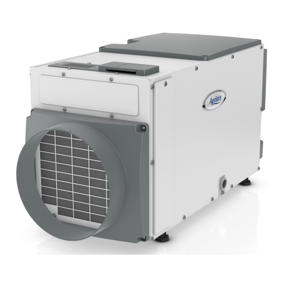
Model 8191 & 8192 Ventilator with Dehumidification
time setting
Inlet
READ AND SAVE THESE INSTRUCTIONS
Installation and Operating Instructions
Ventilator Control
Filter Access
Door
WARNING
CAUTION
Outlet
Drain
Power
Switch
1
Advertisement
Table of Contents

Related Manuals for Aprilaire 8191


Summary of Contents for Aprilaire 8191
-
Page 1: Safety Instructions
Model 8191 & 8192 Ventilator with Dehumidification Installation and Operating Instructions ON/OFF button Up/Down buttons Ventilator Control Outlet used to turn used to change the ventilator humidity or vent on and off time setting MODE button used to access ventilation time... -
Page 2: Table Of Contents
INTRODUCTION AND COMPLIANCE STATEMENT The Model 8191 and 8192 Ventilator with Dehumidification is designed to bring outdoor air into today’s efficiently designed homes while removing moisture from the air . Simply duct the inlet of the ventilator to an outdoor air intake and duct the discharge to the return side of the HVAC system . -
Page 3: Specifications
8A operating current @ 80°F, 60%RH Inlet Air Conditions Ventilation: 40°F – 140°F, 0%RH – 99%RH (non-condensing) Dehumidification: 50°F – 104°F, 40°F dew point minimum Filter MERV 8, washable TABLE 1A – Model 8191 Ventilation Performance External Static CFM/watt (“w.c.) Airflow (CFM) Power (W) -
Page 4: Set Up Ventilator For Installation
SET UP VENTILATOR FOR INSTALLATION IMPORTANT: Cut the strap securing the compressor FIGURE 1 – Remove Shipping Bracket shipping support bracket and remove the strap and shipping bracket . See Figure 1 . REMOVE SHIPPING BRACKET CLIP OFF PLASTIC STRAP 90-1908 DUCT COLLARS STANDARD BASEMENT AND ATTIC INSTALLATIONS... -
Page 5: Control Location
SET UP VENTILATOR FOR INSTALLATION (CONTINUED) CONTROL LOCATION The on-board control can be located on the top of the ventilator or can be relocated to the front of the FIGURE 3 – Control Location ventilator . CONTROL To move the control: PANEL COVER CONTROL 1 . -
Page 6: Drain Installation
DRAIN INSTALLATION The drain outlet on the ventilator can be hard piped using 3/4” nominal drain tubing or the provided fitting and 1/2” clear PVC tubing can be used to drain the ventilator . Always maintain a constant downward slope from the ventilator to the drain and do not allow soft tubing to curl up which may result in air lock . -
Page 7: Ducting And Wiring
. The ventilation output of a thermostat can wired to the DH terminals of the Model 8191 or 8192 to put control of + - A B ODT VENT DEH... -
Page 8: Determine Ventilation Requirements
DETERMINE VENTILATION REQUIREMENTS CALCULATING AIRFLOW REQUIREMENT 1 . The MINIMUM ventilation requirement is calculated using ASHRAE TABLE 2 – CFM Required 62 .2-2010 . Number of Bedrooms ASHRAE Airflow in CFM = [House Area in Sq . Ft . x 0 .01] + House Sq. -
Page 9: System Set Up And Checkout
90-1854 90-1854 External Ventilation Control Option 90-1854 Vent-Auto-C: Ventilation Ventilation settings are adjusted prevented when outdoor on the 8191/8192 (on-board temperature is above 100°F . control) with External Control DISABLED . 90-1854 90-1854 Vent-Auto-D: Ventilation An external control such as a... -
Page 10: Deh W/Ac
SYSTEM SET-UP & CHECKOUT (CONTINUED) DEH W/AC Installer Test Mode If everything is properly wired, the ventilator and all of the wired To allow the ventilator to components will turn on and off during Installer Test Mode to dehumidify during active air demonstrate that all are properly operating . -
Page 11: Start Up And Sequence Of Operation
If an external control has been wired to the thermostat, ventilation will occur only when a circuit is completed between the DH terminals of the Model 8191/8192 control . The external control determines when ventilation occurs . Dehumidification of the incoming air is still controlled as described below even if an external control is determining when to ventilate . -
Page 12: Maintenance
MAINTENANCE CLEAN OR REPLACE THE AIR FILTER After initial installation the air filter should be checked and cleaned every 6 months . The CLEAN FILTER service reminder will display on the on-board control screen every 6 months . To clear the service message, press the UP and DOWN arrows simultaneously for 3 seconds . -
Page 13: Troubleshooting
TROUBLESHOOTING Technical Support is available Monday through Friday, 7:00 a .m . to 5:00 p .m . CST, at (800) 334-6011 . Use the guides on the following pages to identify and correct system faults . Contact Technical Support before replacing the unit or any components and for additional troubleshooting . DIAGNOSTIC CODES When an error occurs, the Diagnostic Code along with SERVICE REQUIRED will be displayed on the control screen . - Page 14 TROUBLESHOOTING (CONTINUED) TABLE 6 – Troubleshooting Guide Symptom Possible Reason Troubleshooting Procedure Ventilator does not turn No power to unit . • Check that the ventilator is plugged in . on/run . • Check that the power switch is turned ON . •...
-
Page 15: Service Parts
Door, Filter Access 5448 Leveling Foot 5457 Outlet Duct Panel 5449 Capacitor, 45MFD, 370VAC 5458 Backflow Damper, 10” 5450 Model 8191 Capacitor, 8MFD, 450VAC 5459 Inlet Duct Panel 5451 Model 8192 Capacitor, 12MFD, 450VAC 5468 Cover, Outlet 5452 RH Sensor 5460... - Page 16 P .O . Box 1467 • Madison, WI 53701-1467 • Phone: 800/334-6011 • Fax: 608/257-4357 • www.aprilairepartners.com 10010925 4 .17 Printed in U .S .A . B2206395E © 2017 Aprilaire – A division of Research Products Corporation...
Need help?
Do you have a question about the 8191 and is the answer not in the manual?
Questions and answers