
Summary of Contents for Tonghui Electronics TH7105
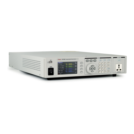
- Page 1 Operation Manual TH7105/7110/7120 Programmable AC Power Source V1.0.6@2019.6 Tonghui Electronic Co.,Ltd. www.tonghui.com.cn...
-
Page 2: Table Of Contents
TH7100 Operation Manual Contents Chapter 1 Introduction ......................1 Introduction of the Instrument ................1 Working Condition ....................2 1.2.1 Power Connection ..................2 1.2.2 Environment Temperature and humidity ............2 1.2.3 Precautions for usage ..................2 1.2.4 Warm-up ......................3 Safety and Symbols ..................... - Page 3 TH7100 Operation Manual 3.4.1 System Environment ..................37 3.4.2 System Communication ..................39 3.4.3 System Tool ...................... 41 Chapter 4 File Management ....................43 Internal File ....................... 43 4.1.1 Description ......................43 4.1.2 Operation ......................43 External File ...................... 44 4.2.1 Description ......................
- Page 4 TH7100 Operation Manual 6.3.4 DISPlay Subsystem Commands ................. 66 6.3.5 :FUNCtion Subsystem Commands ..............67 6.3.6 FETCH Subsystem Commands ................89 6.3.7 SYStem Subsystem Commands ................ 91 MODBUS Communication Commands ............. 97 6.4.1 MODBUS Protocol .................... 97 6.4.2 MODBUS Write Commands ................99 6.4.3 MODBUS Read Commands ................
- Page 5 TH7100 Operation Manual Declaration The descriptions contained in this manual may not cover all information about this instrument. Introductions to the improvements of the instrument in performance, function, internal structure, outer appearance, accessories, packing material, etc. are subject to change without notice. If you find any inconformity of this manual with our instruments, please contact us for further consultation by the address listed on the cover.
-
Page 6: Chapter 1 Introduction
Support over setting current protection (HI-A), over voltage protection (OVP), low-voltage protection (LVP), over current protection (OCP), over power protection (OPP), over temperature protection (OTP) Th7100 series single-phase programmable AC power supply includes the following models: Model Voltage Current Power TH7105 300V 4.2A 500W TH7110 300V 8.4A... -
Page 7: Working Condition
1.2 Working Condition Power Connection 1.2.1 Power supply: 100~120Vac or 198~242Vac Power supply frequencies: 47~63Hz Power range: ≥80VA The power input line L, zero-line N and ground-line E should be the same as the power plug of this instrument. Remove the protection cover on the rear panel before use of the instrument, the detailed wire connection diagram is shown in figure 1-1: Figure 1-1 Environment Temperature and humidity... -
Page 8: Warm-Up
Please do not use damaged equipment. Before use of the instrument, please check if there are any cracks on the shell. Please connect the device with the provided cable. Before operating the instrument, make sure the AC power supply is well grounded. Before connecting to the device, check all the security labels on the device. -
Page 9: Laws And Regulations
Shock hazard sign Table 1-3 Laws and regulations 1.3.2 CE label indicates that the instrument complies with all relevant European laws (a year indicates the year in which the design was approved). This device complies with the marking requirements of WEEE directive (2002/96/EC), and this additional product label states that this appliance/electronic product should not be discarded in household waste. -
Page 10: Chapter 2 Introduction
Chapter 2 Introduction The content of this chapter is just a general description. It mainly introduces the front and rear panel, display area, boot interface and basic operation. Please refer to chapter 3 for detailed introduction. 2.1 Introduction to Front Panel TH7100 series programmable AC power supply front panel is shown in figure 2-1. -
Page 11: Display Zoon
Figure 2-2 Index Name Function Synchronism When output is enabled, it will output a 10V voltage signal from the Signal Socket socket at the same time. Power Input Power terminal and power output terminal Output Terminal Signal Output Output signals of PASS, FAIL, and PROCESSING for automation Terminal devices. -
Page 12: Basic Operation
Figure 2-3 display description 1) Main menu zone This area indicates the name of the current page 2) Parameters setup zone This area is used to modify the test parameters 3) Status zone This area is used to display various prompt information and various status information during system testing. 4) Measurement result display zone This area shows the parameter results of the test. -
Page 13: Programmable Mode
output frequency by the numeric keys and ENTER key. 5) Test output: Press the DISP button, then press the ON/OFF button to output. 2.4.1 Programmable Mode 1) Set the output mode: press the SETUP key, then press the PROG SETUP function key 2) Set the sequence setting parameters: Press the direction key... -
Page 15: Chapter 3 Basic Operations And Description
Chapter 3 Basic Operations and Description This chapter mainly introduces the description and operation of the setting parameters under the <Measurement Display> page, the description and operation of the soft key area buttons, and the description of the status area; Description and operation of setting parameters under <Manual mode> page; Description and operation of setting parameters under <Programmable mode>... - Page 16 Figure 3-2 Programmable Mode <Measurement Display> page 3.1.1.1 Parameter setting description and operation Memory 1) Description In manual mode, this parameter value indicates memory group number, and there are 1~50 memory groups in total. In the programmable mode, the first number indicates the memory group number, and there are 1~50 memory groups in total;...
- Page 17 Current (IRMS_H) 1)Description This parameter represents the current upper limit setting. When the setting voltage is not greater than 150V, the range is 0.000~8.400A; When the setting voltage is greater than 150V, the setting range is 0.000~4.200A. When set to 0.000, the current upper limit function is turned off. In manual mode, this parameter can be changed quickly by I-SET button.
- Page 18 2)Operation Press the key or knob to move the cursor to this parameter option, change the value via the front panel numeric keys, then press ENTER or OK to confirm. When changing the value with the numeric keys, if you do not want to change the parameter value or press the wrong numeric key, you can cancel it by pressing the ...
- Page 19 Figure 3-4 MESA3 Key 2)Operation Under the <Measurement Display> page, press the MESA3 key of the soft key area, then press the PWR or APK or PF or CF as needed to switch output parameters of MESA 3. MESA4 SETUP 1)Description This soft-key is used to configure the parameters required for MESA4, press this soft-key to select the power (PWR)、peak current (APK)、power factor (PF)、crest factor (CF).
-
Page 20: Test Status Instruction
1) Description This key is the voltage mode setting key, which can be set to “AUTO” or “HIGH”. When the voltage mode is set to “AUTO”, it will automatically judge whether the voltage is high or low based on the setting voltage. - Page 21 Figure 3-7 PROG SETUP Mode <MeasDisp> Page 3.1.2.1 Soft key Instruction and Operation PARA DISP 1) Description This soft key is used to switch display of output parameters. When pressed, all output parameters are displayed. 2) Operation Under <MeasDisp> page, press the PARA DISP soft key to switch the display of output parameters. ...
-
Page 22: Manu Setup
Under <MeasDisp> page, press DATA HOLD soft key to keep output constant. Press this key again, the output will change according to real situation. 3.1.2.2 State Zoon Description ON: Output is enabled AUTO: Voltage mode is in “AUTO”, it will automatically judge whether the voltage is high or low based on the setting voltage. - Page 23 Press SETUP button in the front panel, then press MANU SETUP soft key to enter Memory setting page. Make use of the knob or arrow buttons to move the cursor to the desired place and do the parameter setting. 3.2.1.2 Parameter Setting Instruction and Operation ...
- Page 24 2)Operation Press the key or knob to move the cursor to this parameter option, change the value via the front panel numeric keys, then press ENTER or OK to confirm. If you do not want to change the parameter value or press the wrong numeric keys, you can cancel it by pressing the key or ESC key. ...
-
Page 25: Common Setting
This parameter represents the position where the Surge/Drop appears, which can be calculated by the time between this position and the 0 phase point. This parameter is displayed when the Surge/Drop option in <Setup> COMMON page is turned on. When the “SD Cont” is turned on, the range is 0~20ms. - Page 26 parameters under the COMMON setting in <Setup> page. These parameter items are common to all memory sequences under the MEMORY setting. As shown in Figure 3-9: Figure3-9 General Setting<Manual Mode> 2) Operation Press SETUP key, select <Manual Mode>, then make use of the knob and the button to move the cursor to the COMMON option.
- Page 27 F HiLmt 1) Description This parameter is used to set the high limit of output frequency. Its range is 45.0~500.0Hz. 2) Operation Make use of the key or the knob to move the cursor to this parameter option, then change it through the front panel numeric keys, then press ENTER or OK to confirm the change.
- Page 28 This parameter is used to set the status of the display page of the last test result, there are three modes: “LAST”, “ALL” and “P/F”. When set to "LAST", the display will show the final test result after the test is over; When set to “ALL”, the display will show all test results after the test is over; When set to “P/F”, the display will show “PASS”...
-
Page 29: Programmable Mode
the dimming mode function. 2) Operation Make use of the key or the knob to move the cursor to this parameter option, the soft-key zone displays the function menu of this parameter. This parameter can be changed to OFF, Front, or BACK. ... - Page 30 Figure 3-10 Sequence setting page 1 in <programmable mode> Figure 3-11 Sequence setting page 2 in <programmable mode> Figure 3-12 Sequence setting page 3 in <programmable mode>...
- Page 31 3) Operation Press the SETUP button, then select PROG SETUP option. Make use of arrow keys or the knob or the page up/page down soft keys to switch to different pages. 3.3.1.2 Setting Parameters Description and Operation Memory 1) Description In the programmable mode, the parameter value indicates the memory group number, and there are 1~50 memory groups.
- Page 32 StepCycle 1) Description In programmable mode, this parameter represents the number of cycle of the current step. When this parameter is “0”, it will keep testing until the user presses the ON/OFF button or run into errors; When it is set to 1~999, it indicates the number of cycles of the current step. See the programmable mode output function for details.
- Page 33 Make use of the key or the knob to move the cursor to this parameter option, then change it with the front panel numeric keys, and finish with ENTER or OK keys to confirm the change. If you do not want to change the parameter value or press the wrong numeric key when changing with the numeric keys, you can cancel it by pressing the ...
- Page 34 factory settings from M1-1 to M50-9 have the same setting, and each step of the memory needs to be turned on, after the connection test is completed, the next memory can be executed. For example, in memory 1, only the step connection of step 1, step 2, step 3, and step 4 is set to "ON", and the step connection of step 1 of the memory 2 is set to "ON", only M1-1, M1- 2, M1-3, M1-4 are executed, M2-1 will not be executed, because the step connections of M1-5, M1-6, M1-7, M1-8, M1-9 are “OFF”.
- Page 35 the front panel numeric keys, and finish with ENTER or OK keys to confirm the change. If you do not want to change the parameter value or press the wrong numeric key when changing with the numeric keys, you can cancel it by pressing the key or ESC key. ...
- Page 36 Make use of the key or the knob to move the cursor to this parameter option, the soft-key area displays the function menu of this parameter. This parameter can be changed by SEC , MIN or HOUR Soft keys. ...
- Page 37 want to change the parameter value or press the wrong numeric key when changing with the numeric keys, you can cancel it by pressing the key or ESC key. SD Volt 1) Description This parameter indicates the operating voltage of surge/drop, which ranges from 0.0 to 300V. When the parameter value is greater than the set voltage, it is a surge;...
-
Page 38: Common Setting
Description This parameter indicates whether the Surge or Drop is triggered automatically or manually. When this parameter is set to “ON”, press ON/OFF button, the system will execute the trigger action continuously, sending a Surge or Drop wave every 100ms. When this parameter is set to “OFF”, press ON/OFF button, the instrument will execute trigger action every time when pressing TRIG button. - Page 39 1) Description This parameter is used to set the upper limit of the output voltage, which ranges from 0.0 to 300.0V. 2) Operation Make use of the key or the knob to move the cursor to this parameter option, then change it with the front panel numeric keys, and finish with ENTER or OK keys to confirm the change.
- Page 40 This parameter is used to set the starting angle phase of the output waveform, which ranges from 0 to 359°. 2) Operation Make use of the key or the knob to move the cursor to this parameter option, then change it with the front panel numeric keys, and finish with ENTER or OK keys to confirm the change.
- Page 41 displays the function menu for this parameter, this parameter can be changed via the soft-key ON or OC Fold 1) Description This parameter is used to set whether to enable the over-current fold function. When this parameter is set to "ON", the output voltage will decrease due to the load increased, the current output will be kept constant at current high limit.
-
Page 42: System Setting
3.4 <System Setting> 3.4.1 System Environment 3.4.1.1 Description and Operation 1) Description Under the SysEnv of <SysSetup>, users can set system language, pass beep, fail beep, password, alarm beep, key beep, time, date and other parameters. As shown in Figure 3-14. Figure 3-14 system environment of <System Setting>... - Page 43 1) Description This parameter is used to set the instrument password. The instrument is shipped without a password. When the password is turned on, re-boot the instrument requires a password. Please keep the password in mind. 2) Operation Make use of the key or the knob to move the cursor to this parameter option, the soft-key area displays the function menu of this parameter.
-
Page 44: System Communication
Date 1) Description This parameter is used to set the date of the system. 2) Operation Make use of the key or the knob to move the cursor to this parameter option, then change it with the front panel numeric keys, and finish with ENTER or OK keys to confirm the change. If you do not want to change the parameter value or press the wrong numeric key when changing with the numeric keys, you can cancel it by pressing the ... - Page 45 2) Operation Press the SYSTEM button, then press or use the knob to move the cursor to the menu bar, then switch to SysCom page with arrow keys or the knob. 3.4.2.2 Parameters Setting Description and Operation Bus Mode 1) Description This parameter is used to set the communication interface of the instrument.
-
Page 46: System Tool
2) Operation Make use of the key or the knob to move the cursor to this parameter option, the soft-key area displays the function menu of this parameter. This parameter can be changed with soft keys. PLC Onoff 1) Description This parameter is used to set whether the remote control function is enabled. - Page 47 3.4.3.2 Setting Parameters Description and Operation Last State On 1) Description This parameter indicates that the next time while user power on the instrument whether the system would keep the same parameter settings as it was the last time. When set to “ON”, keep the same parameter settings;...
-
Page 48: Chapter 4 File Management
Chapter 4 File Management 4.1 Internal File 4.1.1 Description The TH7100 series programmable AC power supply can store all the parameters that set by the user into the internal non-volatile memory in the form of a file. When users need to use the same settings the next time, users do not need to reset the parameters, just load the corresponding file, you can get the same settings as last time. -
Page 49: External File
3) After the file name is entered, press ENTER or OK to save the file. If the entered file name is the same as the previous file name, a prompt will appear in the prompt bar at the bottom of the screen. If a user did not enter a file name, and pressed ENTER or OK, the default file name is UNNAMExx. -
Page 50: Operation
Figure 4-2 External File The following points should be noted when using a U disk on TH7100 series programmable AC power supply: 1) Use a U disk with USB 2.0 interface. 2) The U disk file system should be FAT16 or FAT32, and formatted using the FAT16 or FAT32 standard; For U disk over 512M, users are advised to use FAT32 standard for formatting. - Page 51 Save 1) Move the key to the serial number of the empty file, then press the save button. 2) A character selection panel will pop up in the center of the screen, move the cursor to your desired place with , , ...
-
Page 52: Chapter 5 Function Introduction
Chapter 5 Function Introduction 5.1 Function Structure Introduction The TH7100 series programmable AC power supply supports manual mode and program control mode. Users can set the system parameters to select manual mode or program control mode. The function structure of the instrument is shown in Figure 5-1. -
Page 53: Programmable Mode Output Function
Figure 5-2 Manual Mode In the programmable mode, there are 50 memory sequences, and each memory sequence includes 9 steps. Each step includes memory number, number of steps, voltage, voltage mode, current high limit, current low limit, frequency, step connection, high limit of pick current, low limit of peak current, power high limit, power low limit, PF high limit, PF low limit, time unit, delay time, dwell time, ramp up time, ramp down time, SD voltage, SD site, SD time, SD connection and other parameters. - Page 54 For example, when the LoopCycle is set to 2, MemoryCycle of memory M1 is set to 1. M1-1:Connect=ON,StepCycle=2; M1-2:Connect=ON,StepCycle=1; M1-3:Connect=ON,StepCycle=2; M1-4:Connect=ON,StepCycle=2; M1-5:Connect=ON,StepCycle=3; M1-6:Connect=ON,StepCycle=1; Then the whole test process is as follows: M1-1M1-1M1-2M1-3M1-3M1-4M1-4M1-5M1-5M1-5M1-6 M1-1M1-1M1-2M1-3M1-3M1-4M1-4M1-5M1-5M1-5M1-6 when the LoopCycle is set to 2, MemoryCycle of memory M1 is set to 2. M1-1:Connect=ON,StepCycle=2;...
-
Page 55: Surge Drop Function
M1-1M1-1M1-2M1-3M1-3M1-4M1-4M1-5M1-5M1-5M1-6M1-7M1-7M1-7 M1-8M1-9M1-9 M1-1M1-1M1-2M1-3M1-3M1-4M1-4M1-5M1-5M1-5M1-6M1-7M1-7M1-7 M1-8M1-9M1-9 M2-1M2-1M2-2M2-2M2-2M2-1M2-1M2-2M2-2M2-2M2-1M2-1M2-2M2-2 M2-2 M1-1M1-1M1-2M1-3M1-3M1-4M1-4M1-5M1-5M1-5M1-6M1-7M1-7M1-7 M1-8M1-9M1-9 M1-1M1-1M1-2M1-3M1-3M1-4M1-4M1-5M1-5M1-5M1-6M1-7M1-7M1-7 M1-8M1-9M1-9 M2-1M2-1M2-2M2-2 M2-2M2-1M2-1M2-2M2-2M2-2 M2-1M2-1M2-2M2-2M2-2 5.3 Surge Drop Function The TH7100 series programmable AC power supply can generate a surge/drop waveform by setting parameters of surge drop voltage, site, time, and connection. ... - Page 56 setting range is 0~99ms. SD Cont This parameter indicates whether the Surge or Drop is triggered automatically or manually. When this parameter is set to “ON”, press ON/OFF button, the system will execute the trigger action continuously, sending a Surge or Drop wave every 100ms. When this parameter is set to “OFF”, press ON/OFF button, the instrument will execute trigger action every time when pressing TRIG button.
-
Page 57: Dimmer Mode Function
Figure 5-5 Auto Triggered Drop 5.4 Dimmer Mode Function This parameter is used to set the front dimmer mode or back dimmer mode. When the dimming mode is turned on, the surge/drop and SD count are enabled by default. In this mode, the manual mode MEMORY setting can only set parameters such as voltage, frequency (45~100Hz), and SD voltage. -
Page 58: Result Display Function
Figure 5-7 Back Dimmer Mode 5.5 Result Display Function The TH7100 series programmable AC power supply provides four result display functions, which are "NONE", "LAST", "ALL", and "P/F". When set to “NONE”, the screen will not display the test results after the test is completed. - Page 59 Figure 5-9 The test result is "LAST" display When set to “ALL”, press the test result key after the test is finished, all the test results will be displayed. Users can save the test results to a USB flash drive for backup. As shown in figure 5-10. Figure 5-10 The test result is "ALL"...
-
Page 60: Protection Function
Figure 5-11 The test result is "P/F" showing "PASS" If it is not in the range, "FAIL" is displayed, and prompt specific parameters that are not within range, as shown in figure 5-12. Figure 5-12 The test result is "P/F" showing "FAIL” 5.6 Protection Function TH7100 series programmable AC power supply provides the following protection: HI-A, OVP, LVP, OCP, OPP, OTP. -
Page 61: Remote Signal Output Function
beep is on), the ON/OFF button indicator flashes. OVP When the voltage output range is from 0V to 150V, and the output voltage exceeds the set voltage 5V, or when the voltage output range is from 0V to 300V, and the output voltage exceeds the set voltage 10V, the display will display “OVP”, alarm beep (when the beep is on), the ON/OFF button indicator flashes. -
Page 62: Remote Control Function
PIN1 and PIN2 to the open state. 2) FAIL Signal Connected between PIN3 and PIN4 relay will Note: After the DUT passes, the relay will connect PIN3 and PIN4. After pressing the Escape key, the return PIN3 and PIN4 to the open state. 3) PROCESSING Signal Connected between PIN5 and PIN6 Note: When the instrument is testing, the relay will connect PIN5 and PIN6. - Page 63 M4 The control switch is connected between PIN1 and PIN5 M5 The control switch is connected between PIN1, PIN8 and PIN5 M6 The control switch is connected between PIN1, PIN9 and PIN5 M7 The control switch is connected between PIN1, PIN8, PIN9 and PIN5 PROGRAM Mode:...
-
Page 64: Chapter 6 Communication Interface
Chapter 6 Communication Interface 6.1 RS232 Interface Description 6.1.1 At present, the widely used serial communication standard is the RS-232 standard, it can also be called the asynchronous serial communication standard, it is used to implement data communication between computers and computers, between computers and peripherals. -
Page 65: Operation
Figure 6-1 RS-232 Interface ————————————————————————————————————————————— Note: The serial port pin definition of this tester is basically the same as the pin definition of the standard 9-core RS232C connector. To avoid electrical shock, turn off the power before plugging or unplugging the connector;... -
Page 66: Usb Virtual Serial Port
Figure 6-3 RS232 Internal pin wiring diagram 6.1.2.2 Transit and Receive Data Format The TH7100 series programmable AC power supply uses a full-duplex asynchronous communication transmission method with start and stop bits. The data transmission format of RS-232 is: 8-bit data bit, 1 bit stop bit, there is no parity bit and the end character is <LF>... -
Page 67: Scpi Communication Commands
CP210xVCPInstaller_x64.exe. After the driver is installed, connect the TH7100 series instrument to the computer with an USB cable. Open the computer device manager, when the port drop-down list shows CP210x USB to UART Bridge Controller (COM3), indicating connection successful. 6.3 SCPI Communication Commands SCPI(Standard Commands for Programmable Instruments), also known as the programmable instrument standard command, it defines the way the bus controller communicates with the instrument. -
Page 68: Command Syntax
6.3.2 Command Syntax 6.3.2.1 Command Key Words and Argument There are two types of common commands and SCPI commands: command with and without argument. Below are some examples: *RST without argument :FORMat <name> with argument(name) :IMMediate without argument There should be at least one space between the command keyword and the argument. Some command words are placed in square brackets, meaning that these command words are optional. - Page 69 3 (,) A comma is used to separate multiple arguments of a command. APPL:SIN455E3,1.15,0.0 4(?) You can query the current value of most parameters by adding a question mark (?) to the command. For example, the following command sets the trigger count to 10:TRIG:COUNT 10.Then, you can query the count value by sending the following command: TRIG:COUNT? 5 Space Must use a blank character, [TAB] or [space] to separate the parameters from the command keyword.
-
Page 70: Common Commands
6.3.2.4 Command Structure Basic Rules Ignore case Example: FUNC:VOLT:DC=func:volt:dc=Func:Volt:Dc Spaces cannot be placed before and after the colon. Example:: FUNC : VOLT : DC wrong, correct: :FUNC:VOLT:DC Commands can be abbreviated or spelled all. Lowercase letters in the command can be omitted. Example: FUNCtion:VOLTage:DC=FUNC:VOLT:DC The command is followed by a question mark (?) to execute a query corresponding to the command. -
Page 71: Display Subsystem Commands
enable register, the power will return a decimal number, this number is the binary weighted sum of all the bits in the enable register. *STB? This command can be used to read the value of the status register. 6.3.4 DISPlay Subsystem Commands DISPlay subsystem commands are mainly used to set the instrument display page. -
Page 72: Function Subsystem Commands
Shorthand for the command: :DISP:PAGE:PROG:MEM3 Command description: Set the display page to: sequence setting page 3 in the programmable mode Command Syntax: :DISPlay:PAGE:PROGram:COMMon Shorthand for the command: :DISP:PAGE:PROG:COMM Command description: Set the display page to: general setting page in program mode Command Syntax: :DISPlay:PAGE:SYSTem:ENV Shorthand for the command: :DISP:PAGE:SYST:ENV Command description:Set the display page to:system environment page under system setting... - Page 73 Figure 6-7 FUNCtion Commands Structure Diagram 6.3.5.1 :FUNC:OUTP Command Syntax: :FUNCtion:OUTPut ON or :FUNCtion:OUTPut 1 Shorthand for command: :FUNC:OUTP ON or :FUNC:OUTP 1 Command description:This command is used to turn on the AC output,this command is only valid under the measurement display page.
- Page 74 Shorthand for command: :FUNC:OUTP OFF or :FUNC:OUTP 0 Command description: This command is used to turn off the AC output,this command is only valid under the measurement display page. Command Syntax: :FUNCtion:OUTPut? Shorthand for command: :FUNC:OUTP? Command description: This command is used to query the current output status, and the command returns 0 or 1.
- Page 75 Command description: This command is used to set the number of the memory sequence in the programmable mode. <value> indicates the number value, and the range is 1~50.The command is invalid when the output is turned on. Command Syntax: :FUNCtion:MEMory:PROGram? Shorthand for command: :FUNC:MEM:PROG? Command description: This command is used to query the number of the memory sequence in the programmable mode, and returns <value>, which is equal to 1~50.
- Page 76 Command description: This command is used to set the number of cycles for the current step in the programmable mode. <value> indicates the value, which ranges from 0 to 999. 6.3.5.5 :FUNC:VOLT Command Syntax: :FUNCtion:VOLTage:MANUal <value> Shorthand for command: :FUNC:VOLT:MANU <value> Command description: This command is used to set the set voltage value in manual mode.
- Page 77 Command Syntax: :FUNCtion:VOLTage: HIghLiMiT:PROGram? Shorthand for command: :FUNC:VOLT:HILMT:PROG? Command description: This command is used to query the high voltage limit value in the manual mode. 6.3.5.7 :FUNC:VOLT:LOLMT Command Syntax: :FUNCtion:VOLTage:LOwLiMiT:MANUal <value> Shorthand for command: :FUNC:VOLT:LOLMT:MANU <value> Command description: This command is used to set the low voltage limit value in the manual mode. <value>...
- Page 78 Shorthand for command: :FUNC:VOLT:MODE:PROG:AUTO Command description: This command is used to set the voltage output of the current step in the programmable mode to the AUTO mode. The command is invalid when the output is turned on. Command Syntax: :FUNCtion:VOLTage:MODE:PROGram:HIGH Shorthand for command: :FUNC:VOLT:MODE:PROG: HIGH Command description: This command is used to set the voltage output of the current step in the programmable mode to the HIGH mode.
- Page 79 0.000~8.400. 6.3.5.10 :FUNC:CURR:LOLMT Command Syntax: :FUNCtion:CURRent:LoWLiMiT:MANUal <value> Shorthand for command: :FUNC:CURR:LOLMT:MAUN <value> Command description: This command is used to set the current low limit value in manual mode, and <value> indicates the current low limit value. When the set voltage is not greater than 150V, the setting range is 0.000~8.400A;...
- Page 80 returns <value>, which is equal to 45.0~500Hz. Command Syntax: :FUNCtion:FREQuncy:PROGram <value> Shorthand for command: :FUNC:FREQ:PROG <value> Command description: This command is used to set the output frequency value of the current step in the programmable mode, and <value> indicates the output frequency value. Its setting range is 45.0~500Hz.
- Page 81 6.3.5.13 :FUNC:FREQ:LOLMT Command Syntax: :FUNCtion:FREQuncy:LOwLiMiT:MANUal <value> Shorthand for command: :FUNC:FREQ:LOLMT:MANU <value> Command description: This command is used to set the low limit of the output frequency in manual mode, and <value> is the low limit of the output frequency. Its setting range is 45.0~500Hz.
- Page 82 step. Returns 0 when the step connection is turned off, and returns 1 when the step connection is turned on. 6.3.5.15 :FUNC:AP:HILMT Command Syntax: :FUNCtion:AmperePeak:HIghLiMiT <value> Shorthand for command: :FUNC:AP:HILMT <value> Command description: This command is used to set the peak current high limit value of the current step in the programmable mode, and <value>...
- Page 83 Command description: This command is used to set the power high limit of the current step in the programmable mode. <value> represents the peak power high limit value, and the range is 0~1000W. The command is invalid when the output is turned on. Command Syntax: :FUNCtion:POWer:HIghLiMiT? Shorthand for command: :FUNC:POW:HILMT? Command description: This command is used to query the power high limit of the current step in the...
- Page 84 6.3.5.20 :FUNC:PF:LOLMT Command Syntax: :FUNCtion:PowerFactor:LOwLiMiT <value> Shorthand for command: :FUNC:PF:LOLMT <value> Command description: This command is used to set the power factor low limit value of the current step in the programmable mode, and <value> indicates the peak power factor low limit value, which ranges from 0 to 1000W.
- Page 85 Command Syntax: :FUNCtion:DWELL? Shorthand for command: :FUNC:DWELL? Command description: This command is used to query the test time of the current step in the programmable mode. Returns <value>, when the unit is second, its value is 0.1~999.9s; when the unit is minute, its value is 0.1~999.9m; when the unit is time, its value is 0.1~999.9h.
- Page 86 Shorthand for command: :FUNC: TIME:SEC? Command description: This command is used to query the seconds value of the timer in manual mode. It returns <value> and its value is equal to 0~59. Command Syntax: :FUNCtion:TIME:MINute <value> Shorthand for command: :FUNC:TIME:MIN <value> Command description: This command is used to set the score of the timer in manual mode.
- Page 87 minute, it returns 1; when the unit is time, it returns 2. The command is invalid when the output is turned on. 6.3.5.25 :FUNC:SD Command Syntax: :FUNCtion:SurgeDrop:MANUal ON or :FUNCtion:SurgeDrop:MANUal 1 Shorthand for command: :FUNC:SD:MANU ON or :FUNC:SD:MANU 1 Command description: This command is used to enable the surge drop function in manual mode.
- Page 88 Shorthand for command: :FUNC:SD:VOLT:PROG <value> Command description:This command is used to set the voltage value of the surge drop at the current step in the programmable mode. <value> indicates the value of the surge drop voltage, ranging from 0.0 to 300.0V. The command is invalid when the output is turned on.
- Page 89 Shorthand for command: :FUNC:SD:TIME:PROG <value> Command description: This command is used to set the time width of the surge drop at the current step in the programmable mode. <value> indicates the time width of the surge drop, ranging from 0 to 20 ms. The command is invalid when the output is turned on. Command Syntax: :FUNCtion:SurgeDrop:TIME:PROGram? Shorthand for command: :FUNC:SD:TIME:PROG? Command description: This command is used to set the time width of the surge drop at the current step...
- Page 90 Command description: This command is used to query the step connection switch status of the current step. Returns 0 when the step connection is turned off, and returns 1 when the step connection is turned on. 6.3.5.26 :FUNC:SANG Command Syntax: :FUNCtion:StartANGle:MANUal <value> Shorthand for command: :FUNC:SANG:MANU <value>...
- Page 91 Command description: This command is used to set the end angle of the current step in the programmable mode. <value> indicates the end angle, and the range is 0~359°. The command is invalid when the output is turned on. Command Syntax: :FUNCtion:EndANGle:PROGram? Shorthand for command: :FUNC:EANG:PROG? Command description: This command is used to query the termination angle of the current step in the programmable mode, and returns <value>, which is equal to 0~359.
- Page 92 Command Syntax: :FUNCtion:RESULT:PROGram P/F or :FUNCtion:RESULT:PROGram 2 Shorthand for command: :FUNC:RESULT:PROG P/F or :FUNC:RESULT:PROG 2 Command description: This command is used to set the result display mode to P/F in the program mode. The command is invalid when the output is turned on. Command Syntax: :FUNCtion:RESULT:PROGram? Shorthand for command: :FUNC:RESULT:PROG? Command description: This command is used to query the result display mode in the programmable...
- Page 93 Command Syntax: :FUNCtion:OverCurrentFold:MANUal? Shorthand for command: :FUNC:OCF:MANU? Command description: This command is used to query the state of over current fold in manual mode. Returns 1 when the over current fold function is on, and 0 when the over current fold function is off.
-
Page 94: Fetch Subsystem Commands
sequence in the programmable mode. Returns <value> with a value equal to 0~999. 6.3.5.34 :FUNC: SS Command Syntax: :FUNCtion:SingleStep ON or :FUNCtion:SingleStep 1 Shorthand for command: :FUNC:SS ON or :FUNC:SS 1 Command description: This command is used to turn on the single step test function in the programmable mode. - Page 95 Figure 6-8 FETCH Command Diagram 6.3.6.1 :FETCH: VOLT? Command Syntax: :FETCH:VOLTage? Shorthand for command: :FETCH:VOLT? Command description: This command is used to query the output voltage value in manual mode, and the command is valid when the output is turned on. 6.3.6.2 :FETCH: CURR? Command Syntax: :FETCH:FETCH:CURRent? Shorthand for command: :FETCH:CURR?
-
Page 96: System Subsystem Commands
6.3.6.5 :FETCH: PF? Command Syntax: :FETCH:PowerFactor? Shorthand for command: :FETCH:PF? Command description: This command is used to query the power factor in manual mode, and the command is valid when the output is turned on. 6.3.6.6 :FETCH: CF? Command Syntax: :FETCH:CrestFactor? Shorthand for command: :FETCH:CF? Command description: This command is used to query the crest factor value in manual mode, and the command is valid when the output is turned on. - Page 97 Figure 6-9 SYStem Commands Structure Diagram 6.3.7.1 :SYST:BEEP Command Syntax: :SYSTem:BEEP:PASS ON or :SYSTem:BEEP:PASS 1 Shorthand for command: :SYST:BEEP:PASS ON or :SYST:BEEP:PASS 1 Command description: This command is used to enable the passing of the test to produce a pass beep. Command Syntax: :SYSTem:BEEP:PASS OFF or :SYSTem:BEEP:PASS 0 Shorthand for command: :SYST:BEEP:PASS OFF or :SYST:BEEP:PASS 0 Command description: This command is used to turn off the pass beep.
- Page 98 Command Syntax: :SYSTem:BEEP:FAIL OFF or :SYSTem:BEEP:FAIL 0 Shorthand for command: :SYST:BEEP:FAIL OFF or :SYST:BEEP:FAIL 0 Command description: This command is used to turn off the fail beep. Command Syntax: :SYSTem:BEEP:FAIL? Shorthand for command: :SYST:BEEP:FAIL? Command description: This command is used to query the status of the FAIL beep. ...
- Page 99 Command Syntax: :SYSTem:YEAR<value> Shorthand for command: :SYST:YEAR <value> Command description: This command is used to set the system year. <value> can be from 0 to 99 or 2000 to 2099. Command Syntax: :SYSTem:YEAR? Shorthand for command: :SYST:YEAR? Command description: This command is used to query the year of the system time. Returns <value> with a value equal to 2000~2099.
- Page 100 Command Syntax: :SYSTem:TIME:MINute <value> Shorthand for command: :SYST:TIME:MIN <value> Command description: This command is used to set the minute of the system time. <value> ranges from 0 to 59 Command Syntax: :SYSTem:TIME:MINute? Shorthand for command: :SYST:TIME:MIN? Command description: This command is used to query the minute of the system time. Returns <value> , it is 0~59.
- Page 101 Command description: This command is used to not keep the last power on state. Command Syntax: :SYSTem:LastState? Shorthand for command: :SYST:LS? Command description: This command is used to query whether to keep the last boot state. 6.3.7.6 :SYST:RESET Command Syntax: :SYSTem:RESET:FACTory Shorthand for command: :SYST:RESET:FACT Command description: This command is used to reset the instrument to factory settings.
-
Page 102: Modbus Communication Commands
Command description: This command is used to set the instrument interface to English. Command Syntax: :SYSTem:LANGuage? Shorthand for command: :SYST:LANG? Command description: This command is used to query the language used by the instrument. MODBUS Communication Commands MODBUS is a serial communication protocol published by Modicon for communication using programmable logic controllers (PLCs). - Page 103 5) High Byte Count The number of bytes represents the total number of bytes written for this operation.If the data is of type char, the number of bytes is 0x0001; if the data is of type int, the number of bytes is 0x0002; if the data is of type float, the number of bytes is 0x0004.
-
Page 104: Modbus Write Commands
the address. 5) High Byte Count The number of bytes represents the total number of bytes written for this operation. If the data is of type char, the number of bytes is 0x0001; if the data is of type int, the number of bytes is 0x0002; if the data is of type float, the number of bytes is 0x0004. - Page 105 This command is used to set the measure mode to programmable mode. The command is 0x01 invalid when the output is turned on. Address 3 (Measurement Mode) 6.4.2.2 Commands Description This command is used to set the instrument measurement mode. The instruction data byte bit corresponds to the function of the instrument as shown in below tables Send Instruction Format Instrument...
- Page 106 Address 5 (Set Voltage) 6.4.2.4 Commands Description This command is used to set the set voltage value in manual mode. The command data range is 0.0~300.0V. Send Instruction Format Instrument Function High High Number Data byte 1~4 address code address address bytes bytes...
- Page 107 Address 7 (Set Frequency) 6.4.2.6 Commands Description This command is used to set the output frequency value in manual mode. The command data range is 45.0~500Hz. When the frequency is less than 100 Hz, the resolution is 0.1 Hz; when the frequency is not less than 100 Hz, the resolution is 1 Hz.
- Page 108 Address 9 (Current Low Limit) 6.4.2.8 Commands Description This command is used to set the current low limit value in manual mode. When the set voltage is not greater than 150V, the command data range is 0.000~8.400A; when the set voltage is greater than 150V, the command data range is 0.000~4.200A.
- Page 109 Address 11 (SD Position) 6.4.2.10 Commands Description This command is used to set the position where the surge drop appears in manual mode. Instruction data byte 1 ranges from 0 to 20. The command is invalid when the output is turned on. Send Instruction Format Instrument Function...
- Page 110 This command is used to control the step connection of the current step. The command is invalid when the output is turned on. The instruction data byte bit corresponds to the function of the instrument as shown below table: Data Byte Step Connection 0x00 This command is used to turn off the step connection of the current step.
- Page 111 Address 15 (Voltage Low Limit) 6.4.2.14 Commands Description This command is used to set the voltage lower limit value in manual mode. The command data range is 0.0~300.0V. The command is invalid when the output is turned on. Send Instruction Format Instrument Function High...
- Page 112 Address 17 (Frequency Low Limit) 6.4.2.16 Commands Description This command is used to set the low limit of the output frequency in manual mode. When the set voltage is not greater than 150V, the command data range is 45.0~500Hz. When the frequency is less than 100 Hz, the resolution is 0.1 Hz;...
- Page 113 Address 19 (End Angle) 6.4.2.18 Commands Description This command is used to set the end angle in manual mode. The command data range is 0~359. The command is invalid when the output is turned on. Send Instruction Format Instrument Function High High Number...
- Page 114 Calculated based on the first 6 1~32 0x10 0x00 0x14 0x00 0x01 bytes Address 21 (Surge Drop) 6.4.2.20 Commands Description This command is used to control the glitch trap in manual mode. The command is invalid when the output is turned on. The instruction data byte bit corresponds to the function of the instrument as shown in below table: Data Byte Step Connection...
- Page 115 0x00 Calculated based 1~32 0x10 0x00 0x16 0x00 0x01 0x02 0x00 on the first 8 bytes 0x01 Return Instruction Format Instrument Function High Address Low Address High bytes Low bytes CRC Low CRC High address Code Calculated based on the first 6 1~32 0x10 0x00...
- Page 116 Calculated based 1~32 0x10 0x00 0x18 0x00 0x01 0x02 0x00 0x00~0x3B on the first 9 bytes Return Instruction Format Instrument Function High Address Low Address High bytes Low bytes CRC Low CRC High address Code Calculated based on the first 6 1~32 0x10 0x00...
- Page 117 Calculated based 1~32 0x10 0x00 0x1A 0x00 0x01 0x01 0x00 0x00~0x63 on the first 9 bytes Return Instruction Format Instrument Function High Address Low Address High bytes Low bytes CRC Low CRC High address Code Calculated based on the first 6 1~32 0x10 0x00...
- Page 118 0~999 0~999 Calculated based 1~32 0x10 0x00 0x1C 0x00 0x01 0x02 High on the first 9 8-bit 8-bit bytes Return Instruction Format Instrument Function High Address Low Address High bytes Low bytes CRC Low CRC High address Code Calculated based on the first 6 1~32 0x10 0x00...
- Page 119 0~999 0~999 Calculated based 1~32 0x10 0x00 0x1E 0x00 0x01 0x02 High on the first 9 8-bit 8-bit bytes Return Instruction Format Instrument Function High Address Low Address High bytes Low bytes CRC Low CRC High address Code Calculated based on the first 6 1~32 0x10 0x00...
- Page 120 Instrument Function High High Number Data Data address code address address bytes bytes of data byte 1 byte 2 High 0x00 Calculated based 1~32 0x10 0x00 0x20 0x00 0x01 0x02 0x00 on the first 8 bytes 0x01 Return Instruction Format Instrument Function High Address...
- Page 121 is turned on. Send Instruction Format Instrument Function High High Number Data byte 1~4 address code address address bytes bytes of data High 0.000~8.400 or 0.000~4.200, 4 Calculated based on 1~32 0x10 0x00 0x22 0x00 0x02 0x04 bytes stored in the first 11 bytes float point type Return Instruction Format...
- Page 122 is turned on. The instruction data byte bit corresponds to the step of the current step of the instrument as shown in below table: Data Byte Step Connection Status This command is used to turn on the step connection of the 0x00 current step.
- Page 123 Calculated based on the first 6 1~32 0x10 0x00 0x25 0x00 0x02 bytes Address 38 (AP Low Limit) 6.4.2.37 Command Description This command is used to set the peak current low limit value of the current step in the programmed mode. When the voltage mode is "AUTO"...
- Page 124 Instrument Function High Address Low Address High bytes Low bytes CRC Low CRC High address Code Calculated based on the first 6 1~32 0x10 0x00 0x27 0x00 0x02 bytes Address 40 (Power Low Limit) 6.4.2.39 Command Description This command is used to set the power low limit of the current step in the programmed mode. The command data range is from 0.0 to 1000W.
- Page 125 Calculated based on the first 6 1~32 0x10 0x00 0x29 0x00 0x02 bytes Address 42 (PF Low Limit) 6.4.2.41 Command Description This command is used to set the power factor low limit value of the current step in the programmed mode. Instruction data range is 0.000~1.000.
- Page 126 0x00 or Calculated based 1~32 0x10 0x00 0x2B 0x00 0x01 0x02 0x00 0x01 or on the first 8 bytes 0x02 Return Instruction Format Instrument Function High Address Low Address High bytes Low bytes CRC Low CRC High address Code Calculated based on the first 6 1~32 0x10 0x00...
- Page 127 0.1~999.9, 4 bytes Calculated based on 1~32 0x10 0x00 0x2D 0x00 0x02 0x04 stored in float the first 11 bytes point type Return Instruction Format Instrument Function High Address Low Address High bytes Low bytes CRC Low CRC High address Code Calculated based on the first 6 1~32...
- Page 128 0.0~999.9, 4 bytes Calculated based on 1~32 0x10 0x00 0x2F 0x00 0x02 0x02 stored in float the first 11 bytes point type Return Instruction Format Instrument Function High Address Low Address High bytes Low bytes CRC Low CRC High address Code Calculated based on the first 6 1~32...
- Page 129 Return Instruction Format Instrument Function High Address Low Address High bytes Low bytes CRC Low CRC High address Code Calculated based on the first 6 1~32 0x10 0x00 0x31 0x00 0x01 bytes Address 50 (SD Time) 6.4.2.49 Command Description This command is used to set the time width of the surge drop in the programmed mode. The command data range is 0~20.
- Page 130 0x00 Calculated based 1~32 0x10 0x00 0x33 0x00 0x01 0x01 0x00 on the first 8 bytes 0x01 Return Instruction Format Instrument Function High Address Low Address High bytes Low bytes CRC Low CRC High address Code Calculated based on the first 6 1~32 0x10 0x00...
- Page 131 0.0~300.0V, 4 Calculated based on 1~32 0x10 0x00 0x35 0x00 0x02 0x04 bytes stored in the first 11 bytes float point type Return Instruction Format Instrument Function High Address Low Address High bytes Low bytes CRC Low CRC High address Code Calculated based on the first 6 1~32...
- Page 132 Instrument Function High High Number Data byte 1~4 address code address address bytes bytes of data High 45.0~500.0V, 4 Calculated based on 1~32 0x10 0x00 0x37 0x00 0x02 0x04 bytes stored in the first 11 bytes float point type Return Instruction Format Instrument Function High Address...
- Page 133 0~359 0~359 Calculated based 1~32 0x10 0x00 0x39 0x00 0x01 0x02 High on the first 9 8-bit 8-bit bytes Return Instruction Format Instrument Function High Address Low Address High bytes Low bytes CRC Low CRC High address Code Calculated based on the first 6 1~32 0x10 0x00...
- Page 134 This command is used to control the surge drop in the programmed mode. Command is invalid when output is turned on. The command data byte bit corresponds to the function of the instrument as shown below: Data Byte Step Connection 0x00 This command is used to turn off the surge drop in the program mode.
- Page 135 Return Instruction Format Instrument Function High Address Low Address High bytes Low bytes CRC Low CRC High address Code Calculated based on the first 6 1~32 0x10 0x00 0x3E 0x00 0x01 bytes Address 61 (Total Circle Numbers) 6.4.2.60 Command Description This command is used to set the total number of cycles of the memory sequence in the programmed mode.
-
Page 136: Modbus Read Commands
0x01 bytes 6.4.3 MODBUS Read Commands Address 1 (Instrument Model) 6.4.3.1 Command Description This command is used to query the model number of the instrument. The instrument models are TH7105, TH7110, TH7120. Send Instruction Format Instrument Function High Address Low Address... - Page 137 0x01 0x00 0x01 bytes Return Instruction Format If the instrument model is TH7105, it returns 0x1BC1; if the instrument model is TH7110, it returns 0x1BC6; if the instrument model is TH7120, it returns 0x1BD0. Instrument Function Number of Data Byte1...
- Page 138 Send Instruction Format Instrument Function High Address Low Address High bytes Low bytes CRC Low CRC High address Code Calculated based on the first 6 1~32 0x03 0x00 0x03 0x00 0x01 bytes Return Instruction Format Data Byte returns 0 or 1. 0 means the instrument's test mode is in manual mode; 1 means the instrument's test mode is in programmed mode.
- Page 139 Send Instruction Format Instrument Function High Address Low Address High bytes Low bytes CRC Low CRC High address Code Calculated based on the first 6 1~32 0x03 0x00 0x05 0x00 0x02 bytes Return Instruction Format The return command data byte range is 0.0~300.0V. Instrument Function Code Number of Data...
- Page 140 Send Instruction Format Instrument Function High Address Low Address High bytes Low bytes CRC Low CRC High address Code Calculated based on the first 6 1~32 0x03 0x00 0x07 0x00 0x02 bytes Return Instruction Format The return command data byte range is 45.0~500Hz. When the frequency is less than 100 Hz, the resolution is 0.1 Hz;...
- Page 141 Send Instruction Format Instrument Function High Address Low Address High bytes Low bytes CRC Low CRC High address Code Calculated based on the first 6 1~32 0x03 0x00 0x09 0x00 0x02 bytes Return Instruction Format When the set voltage is not greater than 150V, the return command data range is 0.000~8.400A; when the set voltage is greater than 150V, the return command data range is 0.000~4.200A.
- Page 142 Send Instruction Format Instrument Function High Address Low Address High bytes Low bytes CRC Low CRC High address Code Calculated based on the first 6 1~32 0x03 0x00 0x0B 0x00 0x01 bytes Return Instruction Format The return command data byte range is 0--20. Instrument Function Number of...
- Page 143 Calculated based on the first 6 1~32 0x03 0x00 0x0D 0x00 0x01 bytes Return Instruction Format Data Byte returns 0 or 1. 0 means that the SD connection of the surge drop is off in manual mode; 1 means that the SD connection of the surge drop is turned on in manual mode. Instrument Function Number of...
- Page 144 Calculated based on the first 6 1~32 0x03 0x00 0x0F 0x00 0x02 bytes Return Instruction Format The return command data range is 0.0~300.0V. Instrument Function Code Number of Data Data Byte 1~4 CRC Low CRC High address 0.0~300.0, 4 bytes 1~32 0x03 0x04...
- Page 145 Calculated based on the first 6 1~32 0x03 0x00 0x11 0x00 0x02 bytes Return Instruction Format The return command data range is 45.0~500Hz. When the frequency is less than 100 Hz, the resolution is 0.1 Hz; when the frequency is not less than 100 Hz, the resolution is 1 Hz. Instrument Function Code Number of Data...
- Page 146 Calculated based on the first 6 1~32 0x03 0x00 0x13 0x00 0x02 bytes Return Instruction Format Return command data range is 0~359 Instrument Function Number of Data Byte1 Data Byte2 CRC Low CRC High address Code Data 0~359 High Calculated based on the first 5 1~32 0x03 0x02...
- Page 147 Instrument Function High Address Low Address High bytes Low bytes CRC Low CRC High address Code Calculated based on the first 6 1~32 0x03 0x00 0x15 0x00 0x01 bytes Return Instruction Format Data byte returns 0 or 1.0 indicates that the surge drop is off in manual mode; 1 indicates that the glitch trap is on in manual mode.
- Page 148 voltage in manual mode. Send Instruction Format Instrument Function High Address Low Address High bytes Low bytes CRC Low CRC High address Code Calculated based on the first 6 1~32 0x03 0x00 0x17 0x00 0x02 bytes Return Instruction Format Return instruction data range is 5.0~50.0V. Instrument Function Code Number of Data...
- Page 149 Instrument Function High Address Low Address High bytes Low bytes CRC Low CRC High address Code Calculated based on the first 6 1~32 0x03 0x00 0x19 0x00 0x01 bytes Return Instruction Format Return instruction data byte range is 0~59. Instrument Function Number of Data Byte1...
- Page 150 Calculated based on the first 6 1~32 0x03 0x00 0x1B 0x00 0x01 bytes Return Instruction Format Return instruction data byte range is 1~50. Instrument Function Number of Data Byte1 Data Byte2 CRC Low CRC High address Code Data Calculated based on the first 5 1~32 0x03 0x02...
- Page 151 Return instruction data byte range is 1~9. Instrument Function Number of Data Byte1 Data Byte2 CRC Low CRC High address Code Data Calculated based on the first 5 1~32 0x03 0x02 0x00 bytes Address 30 (Step Frequency) 6.4.3.30 Command Description This command is used to query the number of steps in the programmed mode.
- Page 152 0.0~300.0, 4 bytes 1~32 0x03 0x04 stored in float point Calculated based on the first 7 bytes type Address 32 (Voltage Mode) 6.4.3.32 Command Description This command is used to query the voltage output mode of the current step in the programmed mode. Send Instruction Format Instrument Function...
- Page 153 Instrument Function Code Number of Data Data Byte 1~4 CRC Low CRC High address 0.000~4.200 or 0.000~8.400, 4 bytes 1~32 0x03 0x04 Calculated based on the first 7 bytes stored in float point type Address34 (Current Low Limit) 6.4.3.34 Command Description This command is used to query the current low limit of the current step in the programmed mode.
- Page 154 Return Instruction Format Return instruction data byte range is 45.0~500Hz。When frequency is less than 100Hz,the resolution is 0.1Hz;When frequency is not less than 100Hz,the resolution is 1 Hz. Instrument Function Code Number of Data Data Byte 1~4 CRC Low CRC High address 45.0~500, 4 bytes 1~32...
- Page 155 Calculated based on the first 6 1~32 0x03 0x00 0x25 0x00 0x02 bytes Return Instruction Format When the voltage mode is "AUTO" and the voltage is less than 150V, the range is 0.0~33.6A; when the voltage mode is "AUTO" and the voltage is greater than 150V or the voltage mode is "HIGH", the range is 0.0~16.8A.
- Page 156 Instrument Function High Address Low Address High bytes Low bytes CRC Low CRC High address Code Calculated based on the first 6 1~32 0x03 0x00 0x27 0x00 0x02 bytes Return Instruction Format The return instruction data range is 0.0~1000. When it returns 0.0,it means this function is turned off. Instrument Function Code Number of Data...
- Page 157 Instrument Function High Address Low Address High bytes Low bytes CRC Low CRC High address Code Calculated based on the first 6 1~32 0x03 0x00 0x29 0x00 0x02 bytes Return Instruction Format The return instruction data range is 0.000~1000. When it returns 0.000,it means this function is turned off.
- Page 158 Send Instruction Format Instrument Function High Address Low Address High bytes Low bytes CRC Low CRC High address Code Calculated based on the first 6 1~32 0x03 0x00 0x2B 0x00 0x01 bytes Return Instruction Format The return instruction data is 0x00 or 0x01 or 0x02. When the return command data is 0x00, it means that the time unit of the current step in the programmed mode is seconds;...
- Page 159 Address 45 (Test Time) 6.4.3.45 Command Description This command is used to query the test time of the current step in the programmed mode. Send Instruction Format Instrument Function High Address Low Address High bytes Low bytes CRC Low CRC High address Code Calculated based on the first 6...
- Page 160 Address 47 (Fall Time) 6.4.3.47 Command Description This command is used to query the fall time of the current step in the programmed mode. Send Instruction Format Instrument Function High Address Low Address High bytes Low bytes CRC Low CRC High address Code Calculated based on the first 6...
- Page 161 Address 49 (SD Location) 6.4.3.49 Command Description This command is used to query the location of the surge or drop of the current step in the programmed mode. Send Instruction Format Instrument Function High Address Low Address High bytes Low bytes CRC Low CRC High address...
- Page 162 Address 51 (SD Connection) 6.4.3.51 Command Description This command is used to query the connection status of the glitch or notch of the current step in the programmed mode. Send Instruction Format Instrument Function High Address Low Address High bytes Low bytes CRC Low CRC High...
- Page 163 Address 53 (Voltage Low Limit) 6.4.3.53 Command Description This command is used to query the low limit of the voltage in the programmed mode. Send Instruction Format Instrument Function High Address Low Address High bytes Low bytes CRC Low CRC High address Code Calculated based on the first 6...
- Page 164 Address 55 (Frequency Low Limit) 6.4.3.55 Command Description This command is used to query the low frequency limit value in the programmed mode. Send Instruction Format Instrument Function High Address Low Address High bytes Low bytes CRC Low CRC High address Code Calculated based on the first 6...
- Page 165 Address 57 (End Angle) 6.4.3.57 Command Description This command is used to query the termination angle in the programmed mode. Send Instruction Format Instrument Function High Address Low Address High bytes Low bytes CRC Low CRC High address Code Calculated based on the first 6 1~32 0x03 0x00...
- Page 166 Address 59 (Surge Drop) 6.4.3.59 Command Description This command is used to query the state of the glitch trap in the programmed mode. Send Instruction Format Instrument Function High Address Low Address High bytes Low bytes CRC Low CRC High address Code Calculated based on the first 6...
- Page 167 Address 61 (Total Circle Numbers) 6.4.3.61 Command Description This command is used to query the total number of cycles of the memory sequence in the programmed mode. Send Instruction Format Instrument Function High Address Low Address High bytes Low bytes CRC Low CRC High address...
- Page 168 Address 64 (Output Voltage) 6.4.3.63 Command Description This command is used to obtain the output voltage. The command is valid when the output is turned on. Send Instruction Format Instrument Function High Address Low Address High bytes Low bytes CRC Low CRC High address Code...
- Page 169 Address 66 (Output Power) 6.4.3.65 Command Description This command is used to obtain the output power. The command is valid when the output is turned on. Send Instruction Format Instrument Function High Address Low Address High bytes Low bytes CRC Low CRC High address Code...
- Page 170 Address 68 (Output PF) 6.4.3.67 Command Description This command is used to obtain the output power factor. The command is valid when the output is turned Send Instruction Format Instrument Function High Address Low Address High bytes Low bytes CRC Low CRC High address Code...
-
Page 171: Chapter 7 Technical Specifications
Chapter 7 Technical Specifications 7.1 Product Specifications 7.1.1 AC Input Model TH7105 TH7110 TH7120 Phase 1Ø Voltage 115/230Vac±15% Frequency 47~63Hz Maximum Current 16A/8A 30A/16A Power Factor Table 7-1 AC Input 7.1.2 AC Output Rated Power 500W 1000W 2000W Output Power 0~300Vac... -
Page 172: Measurement
Resolution 1° Table 7-3 Instrument Setup 7.1.4 Measurement Model TH7105 TH7110 TH7120 Range 0~300Vac Voltage Resolution 0.1V Accuracy ±(0.5% readings+2 digits) Range 45.0Hz~500Hz Frequency Resolution 0.1Hz(45.0Hz~99.9Hz);1Hz(100Hz~500Hz) Accuracy ±0.1Hz 0~150Vac 0.000~4.200A 0.000~8.400A 0.000~16.800A Range 0~300Vac 0.000~2.100A 0.000~4.200A 0.000~8.400A Current Resolution 0.001A Accuracy ±(0.5% readings+3 digits) -
Page 173: Dimension
Over-set current protection (HI-A), over voltage protection (OVP), low voltage Protection protection (LVP), over current protection (OCP), over power protection (OPP), over temperature protection (OTP) LCD Display 4.3 inch,480×270 Interface USB COM、RS232、USBHOST Table 7-5 Convention 7.1.6 Dimension Length(mm) Width(mm) Height(mm) Net Weight(Kg)... -
Page 174: Chapter 8 Warranty
Chapter 8 Warranty Warranty period: the warranty period is 1 year. During the warranty period, if the user damages the instrument due to improper operation of the user, the maintenance cost shall be borne by the user. The instrument is responsible for lifelong maintenance by Tonghui. -
Page 175: Chapter 9 Appendix
Chapter 9 Appendix 9.1 Error Message <Measurement display> the status bar display “HI-A” indicates that the output current exceeds the set current high limit, the display “OVP” indicates that the output voltage exceeds the set voltage by 5V or 10V, the display “LVP”... -
Page 176: Func Commands
Table 9-1 DISP Commands List 9.2.2 FUNC Commands Title Commands Description :FUNC:OUTP 0 Turn on AC output Output :FUNC:OUTP 1 Turn off AC output Switch :FUNC:OUTP? Query current output state. Return 0 or 1 :FUNC:RM:MANU Set the test mode as manual Test Mode :FUNC:RM:PROG Set the test mode as programmed control... - Page 177 <value> :FUNC:SD:TIME:MANU? Query the time width of the surge drop in manual mode :FUNC:SD:CT:MANU 0 Turn off SD connection in manual mode :FUNC:SD:CT:MANU 1 Turn on SD connection in manual mode Connectio Query the SD connection status of the current memory :FUNC:SD:CT:MANU? sequence in manual mode.
- Page 178 minutes :FUNC:TIME:MIN? Query the minute value of the timer in manual mode :FUNC:TIME:HOUR <value> Set the hour value of the timer in manual mode Timer hours :FUNC:TIME:HOUR? Query the hour value of the timer in manual mode PROG Set the number of the memory sequence in the programmed :FUNC:MEM:PROG <value>...
- Page 179 :FUNC:CONNECT 1 Turn on the step connection of the current step Query the state of the step connection of the current step. :FUNC:CONNECT? Return 0 or 1. Set the power high limit of the current step in the :FUNC:AP:HILMT <value> programmed mode AP HiLmt Query the power high limit of the current step in the...
- Page 180 Set the ramp up time of the current step in the programmed :FUNC:RAMP:UP <value> mode R_Up Time Query the ramp up time of the current step in the :FUNC:RAMP:UP? programmed mode Set the ramp down time of the current step in the :FUNC:RAMP:DOWN <value programmed mode R_Dn Time...
- Page 181 Set the staring angle of the current step in the programmed :FUNC:SANG:PROG <value> mode ON PHS Query the staring angel of the current step in the :FUNC:SANG:PROG? programmed mode Set the end angle of the current step in the programmed :FUNC:EANG:PROG <value>...
-
Page 182: Syst Commands
9.2.3 SYST Commands Title Commands Description :SYST:BEEP:PASS 0 Turn off the pass beep Pass :SYST:BEEP:PASS 1 Turn on the pass beep Beep :SYST:BEEP:PASS? Query the state of pass beep :SYST:BEEP:FAIL 0 Turn off the fail beep Fail :SYST:BEEP:FAIL 1 Turn on the fail beep Beep :SYST:BEEP:FAIL? Query the state of fail beep... -
Page 183: Fetch Commands
Read/Write Return Value Command Description registers 7105 Read the instrument model number. 7105 indicates that the instrument model is TH7105, 7110 indicates that the Read 7110 instrument model is TH7110, and 7120 indicates that the instrument model is TH7120. 7120 Set or read the status of the output switch. - Page 184 Read/Write 0~4.2or0~8.4 Set or query the current high limit in manual mode Read/Write 0~4.2or0~8.4 Set or query the current low limit in manual mode Read/Write 0~300 Set or query the voltage of the surge drop in manual mode Read/Write 0~99or0~20 Set or query the site of the surge drop in manual mode Set or query the time width of the surge drop in manual Read/Write...
- Page 185 Read/Write 0~999 Set or query the sequence times in the programmed mode Set or query the number of steps in the programmed Read/Write mode Set or query the number of steps of the current memory Read/Write 0~999 sequence in the programmed mode Read/Write 0~300 Set or query the set voltage in the programmed mode...
- Page 186 Set or query the ramp down time of the current step in Read/Write 0.1~999.9 the programmed mode Set or query the voltage of the surge drop in the Read/Write 0~300 programmed mode Set or query the position where the surge drop appears in Read/Write 0~99or0~20 the programmed mode.
-
Page 187: Manual Amendment Description
Read 0~300 Read the measured voltage Read 0~4.2or0~8.4 Read the measured current Read 0~1000 Read the measured power Read 0~4.2or0~8.4 Read the measured ampere peak Read Read the measured power factor Read Read the measured crest factor Table 9-5 MODBUS Commands 9.4 Manual Amendment Description V1.0.0-------------------------------------------------------------------------------------------------------------2017.12 V1.0.1-------------------------------------------------------------------------------------------------------------2017.12...
Need help?
Do you have a question about the TH7105 and is the answer not in the manual?
Questions and answers