Table of Contents
Advertisement
Instruction Manual
Par ts List
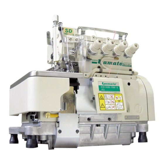
Thank you f or purchasing BT43.
For pr operly your BT43, please r ead over this manual and the manual f or sewing machine
together to fully under stand their contents.
A f ter r eading the instruc tion manual, please keep it in a location wher e it is easily acces-
sible to the oper ator.
MANUAL BACK-TACKING DEVICE
AZ7000SD-8, AZ8000SD-8, AZF8000G class
BT43
Advertisement
Table of Contents

Summary of Contents for Yamato BT43
- Page 1 AZ7000SD-8, AZ8000SD-8, AZF8000G class Thank you f or purchasing BT43. For pr operly your BT43, please r ead over this manual and the manual f or sewing machine together to fully under stand their contents. A f ter r eading the instruc tion manual, please keep it in a location wher e it is easily acces-...
-
Page 2: Table Of Contents
CONTENTS 1. Overview 2. Installation Check and change of voltage Control box Installation Wiring diagram Power cord connection Precautions Synchronizer installation Automatic motor stop function Automatic presser foot lifter device (special order parts) 3. Proper operation Seam condition and device operation Each section name and function of control panel Adjustment at beginning of sewing 3.3.1... - Page 3 CONTENTS 6. Test mode usage Solenoid function test Reset Fabric sensor function test * * * * ILLUSTRATED PARTS LIST * * * * Attention ◇This instruction manual is designed mainly for technicians, but it is advisable that also operators read the instructions with mark to use the machine properly.
-
Page 4: Overview
2-needle machine for AZ7000SD-8 class, AZ8000SD-8 class and AZF8000G class Features: ◇ This BT43 device is applied to both stable seam condition on the material and beautiful back-tacking of soft thread chain into the seam by using the movable middle stitch plate tongue and tension releaser interlocked with the electrooptical function for detecting the material. -
Page 5: Installation
At shipment, the voltage printed on the control box is 220 V and the usable range is 220 to 240 V. If using this BT43 device at a voltage other than this range, please contact our technician in our agencies. -
Page 6: Control Box Installation
2.Installation 2.2 Control box installation Install the control box under the table with the wood screws referring to Fig.2-2. control box 280 ㎜ 20 ㎜ operator 70 ㎜ Fig. 2-2 AZ-SD, AZF-G/BT43... -
Page 7: Wiring Diagram
4P white rotation detector unit 2P white stitch plate tongue solenoid intermediate 2P blue cable 3P white tension releaser fabric detection solenoid sensor Fig. 2-3 AZ-SD, AZF-G/BT43... -
Page 8: Power Cord Connection
◇ Even if the glass tube for the fuse has the same Table 3 size as applicable one, its capacity may be different. Be sure to check the printed capacity. Using a fuse with inapplicable capacity can damage the machine. AZ-SD, AZF-G/BT43... -
Page 9: Synchronizer Installation
2.Installation 2.6 Synchronizer installation ① For a machine with this BT43 device, use always a positioner motor. (1) Set the motor to Position 1. (2) Install the synchronizer ① to the machine and tighten it lightly with the screws ② . (3) Fasten the synchronizer ① to the machine ②... -
Page 10: Automatic Presser Foot Lifter Device (Special Order Parts)
2.8.1 Installing presser foot lifter mechanism (1) Install the regulator and the solenoid valve on the proper position under the machine table. (2) Set the air cylinder ① on the rear of the machine. Insert the groove of the lifter holder ② to the lifter lever ③ . ① ① ② ② ② ③ ③ ③ ② ③ Fig. 2-9 Fig. 2-8 AZ-SD, AZF-G/BT43... - Page 11 Refer to Fig. 2-10 to connect the air tubes. Cut the tubes properly for the connection. Set the regulator at 0.2 to 0.4 MPa. presser foot lifter cylinder 4 × 2.5 ㎜ 4 × 2.5 ㎜ solenoid vale 6 × 4 ㎜ to air source regulator Fig. 2-10 AZ-SD, AZF-G/BT43...
- Page 12 (Fig. 2-12) Option A(white 12P) black wire ① to pin No. 10 for “0V” to pin No. 4 for “ Up position white wire ② ① ② stop input” Presser foot lifer(blue 3P) white wire ② to pin No. 2 for “Presser foot input” Fig. 2-12 AZ-SD, AZF-G/BT43...
-
Page 13: Proper Operation
(5) Bring the thread chain to the front. Pull the thread chain from the left to the right along the cloth plate. Then, the thread chain cutter cuts the thread chain and holds the remaining portion. Repeat Steps (3) to (5). AZ-SD, AZF-G/BT43... -
Page 14: Each Section Name And Function Of Control Panel
⑦ “ END” lamp This is lighted when the count at the end of sewing is adjusted. ⑧ “ TENSION”/“TONGUE” lamp This shows the current setting mode by combination with other lamps. ⑨ Display This displays the set value. AZ-SD, AZF-G/BT43... -
Page 15: Adjustment At Beginning Of Sewing
(2) Adjust the count by pressing the “ ▲” and “ ▼” keys so that the stitch plate tongue sticks out when the sensor detects the material end and the material reaches the needle holes. (Two counts indicate one stitch.) Fig. 3-4 tongue sticks out Fig. 3-5 AZ-SD, AZF-G/BT43... -
Page 16: Adjustment At End Of Sewing
(2) Adjust the count by pressing the “▲” and “▼” keys so that the stitch plate tongue is recessed when the sensor detects the mate- rial end and the material reaches the needle holes. (Two counts indicate one stitch.) Fig. 3-7 tongue is retracted Fig. 3-8 AZ-SD, AZF-G/BT43... -
Page 17: Mesh Materials
(3) Press the “MODE” key several times to light the “START” and “TENSION” lamps. (4) With the “ ▲”and “ ▼” keys, adjust the count from sewing end to motor stop. (Two counts indicate one stitch.) (5) Turn the power OFF. Fig. 3-10 AZ-SD, AZF-G/BT43... -
Page 18: Automatic Presser Foot Lifter Mechanism
(3) Press the “MODE” key several times to light the “START”, “END”, and “TENSION” lamps. (4) With the “ ▲”and “ ▼” keys, adjust the time from material detection of the sensor to presser foot lowering. (5) Turn the power OFF. Fig. 3-11 AZ-SD, AZF-G/BT43... -
Page 19: Adjustments
(4) Tighten the screw ③ securely and fasten a new knife. (5) Fit the pin hole and the slot for the knife of the thread chain presser plate ② on the pin and the knife respectively and return the thread chain presser plate ② to the original position. AZ-SD, AZF-G/BT43... -
Page 20: Lower Looper Adjustment
③ and check that the motor has already stopped. ② To adjust the lower looper of a sewing machine with a BT43 device, take the following steps. (1) Loosen the screws ① and turn the solenoid cover ② in the arrow direction. (2) Loosen the screws ③ and remove the solenoid. -
Page 21: Troubleshooting
The tension releaser or the stitch plate tongue cannot be moved. Change the control The control board is broken. board. Resetting to the default setting cannot be performed. Change the control There is an abnormal state in the memory. board. Table 5 Note: After the above error code is displayed, the control box does not operate. AZ-SD, AZF-G/BT43... - Page 22 ON. (3) Press the “MODE” key several times to light the “START” and “END” lamps. “oo” The fabric sensor is covered. “- -” The fabric sensor is not covered. (4) Turn the power OFF. Fig. 6-3 AZ-SD, AZF-G/BT43...
- Page 23 〒530-0047 大 阪 市 北 区 西 天 満 4 丁 目 4 番1 2 号 T E L(0 6) 6 3 6 4- 5 6 2 1 ( 代 ) F A X(0 6) 6 3 6 4- 7 1 8 5 P/N 9730110(P/I) No.4 Edited in 2011.8 (BT43/AZ-G) Printed in Japan 2011.8.1H Y...
Need help?
Do you have a question about the BT43 and is the answer not in the manual?
Questions and answers