
Summary of Contents for OBO Bettermann EI30
- Page 1 Mounting instructions ® PYROLINE Con PLC fire protection duct EI30-EI90 classification according to EN 13501-2...
- Page 2 Con PLC fire protection duct ® Mounting instructions © 2021 OBO Bettermann Holding GmbH & Co. KG All the personal designations used in the document are to be considered gender-neutral. PYROLINE ® is a registered brand of OBO Bettermann Holding GmbH & Co. KG...
-
Page 3: Table Of Contents
Table of contents Table of contents About these instructions Target group ........5 Relevance of these instructions . - Page 4 Con D PLC ..... .59 ® 11.2 Dismantling PYROLINE Con S PLC ..... .59 ® Disposal Technical data 4 | EN OBO Bettermann...
-
Page 5: About These Instructions
About these instructions About these instructions Target group These instructions are intended for specialists and/or instructed technical personnel (e.g. engineers, architects, heads of construction, and mount- ing and installation engineers) who have had fire protection training and are charged with the installation of the fire protection duct. Relevance of these instructions –... -
Page 6: Applicable Documents
Part 2: Classification using data from fire resistance tests, excluding ventilation services – DIN 4102-4: 2016-05 Fire behaviour of building materials and building components – Part 4: Synopsis and application of classified building materials, compo- nents and special components – EU construction products regulation 6 | EN OBO Bettermann... -
Page 7: Safety
Safety Safety General safety information Observe the following basic safety information on handling the PYROLINE Con PLC fire protection duct: ® – All the appropriate regulations and technical regulations of other units, in particular those for electrical engineering, must be complied with. –... -
Page 8: Product Description, Pyroline ® Con Plc Fire Protection Duct
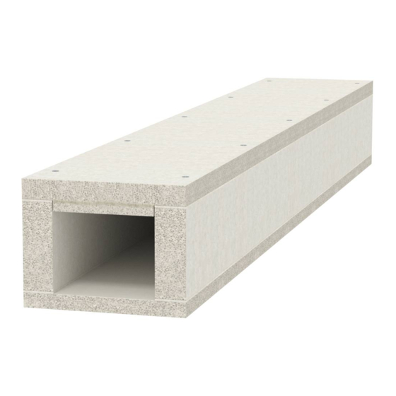
– Fire load encapsulation up to 90 minutes (EI30–EI90 classification) – Material made of non-combustible fibre glass lightweight concrete, water and frost-resistant, non-electrically conductive –... -
Page 9: Product Overview
Product description, PYROLINE® Con PLC fire protection duct Product overview 4 2 1 PYROLINE Con D PLC for direct wall or ceiling mounting ® The PYROLINE Con D PLC product version is mounted directly on the ® wall or ceiling and consists of the following product elements: Fig 1: Product overview, PYROLINE Con D PLC... -
Page 10: Pyroline ® Con S Plc For Mounting With A Support System
Con S PLC for mounting with a support system ® The PYROLINE Con S PLC product version is mounted directly on the ® wall or ceiling and consists of the following product elements: Fig 2: Product overview, PYROLINE Con S PLC ® 10 | EN OBO Bettermann... - Page 11 Product description, PYROLINE® Con PLC fire protection duct Product element Function Duct trough made up of Cable seat, duct walls and duct base support on support system Connection of the joints of two fire With connector protection duct troughs Duct cover with side and (Straight) connection of the fire protec- joint overlap tion duct...
-
Page 12: Selecting The Fire Protection Duct
PLCD D091220 120 x 200 180 x 280 21.0 Tab 3: Fire protection ducts for direct wall/ceiling mounting for EI30–EI60 and EI90 classification Fire protection duct for mounting with a support system Mounting with a support system is particularly useful if obstacles such as heating, ventilation or water pipes or joists must be refitted. -
Page 13: Planning An Installation
Planning an installation Planning an installation To ensure the functionality of the fire protection duct, installations and installation locations must fulfil technical and structural requirements. Structural conditions If there are uncertainties about the load capacity of walls and ceilings, then a structural engineer must be consulted. –... -
Page 14: Approved Cables
PYROLINE Con PLC fire protection duct for fire encapsulation ® (EI30–EI60, EI90) All standard cable types up to a maximum diameter of d = 21 mm, including fibre-optic cables, can always be routed. This excludes hollow core cables and wire cables. -
Page 15: Mounting Pyroline® Con D Plc On A Wall/Ceiling
Mounting PYROLINE® Con D PLC on a wall/ceiling Mounting PYROLINE Con D PLC on a wall/ ® ceiling The PYROLINE Con D PLC fire protection duct is mounted directly on ® the wall in conjunction with separating brackets or under the ceiling with separating clamps. - Page 16 8. Shorten the last duct trough to the wall with a hand or coping saw, removing 3 mm from the residual length for the necessary joints. 9. Apply sealing strips to both front ends of the last duct trough. 16 | EN OBO Bettermann...
- Page 17 Mounting PYROLINE® Con D PLC on a wall/ceiling 10. Mount the last duct trough and ensure a joint of 3 mm to the previous duct trough. Fig 6: Wall connection 11. Fully close the joint to the wall with KTM mortar 12.
-
Page 18: Mounting The Duct Cover
The fire protection duct is fully mounted. If the fire protection duct is run through the wall or meets it, then a wall connection collar must be mounted, see chapter “7.10 Creating a wall connection” on page 32. 18 | EN OBO Bettermann... -
Page 19: Creating A Corner Connection
Mounting PYROLINE® Con D PLC on a wall/ceiling Creating a corner connection Fig 8: 90° internal corner, 90° external corner To run cables round room corners, it is possible to create 90° internal and external corners with the PYROLINE Con D PLC product version. ®... - Page 20 10. Stick the sealing strip all along the support surface and the shortened front side of the duct cover 11. Mount the duct cover along the marking lines with counter-sunk head screws on the duct trough 20 | EN OBO Bettermann...
-
Page 21: 90° External Corner
Mounting PYROLINE® Con D PLC on a wall/ceiling 7 3 2 90° external corner Fig 11: 90° external corner duct trough mounting 1. Shorten the duct trough to the necessary dimension, so that they end flush to the wall corner. Take the maximum 3 mm joint with the sealing strip into account. - Page 22 9. Stick the sealing strip all along the support surface and at the notched out point of the duct cover 10. Mount the duct cover along the marking lines with counter-sunk head screws on the duct trough 22 | EN OBO Bettermann...
-
Page 23: Creating A 90° Flat Angle
Mounting PYROLINE® Con D PLC on a wall/ceiling Creating a 90° flat angle Fig 13: 90° flat angle To run cables on at a 90° angle, it is possible to create 90° flat angles with the PYROLINE Con D PLC product version. During mounting, ®... - Page 24 11. Stick the sealing strip all along the support surface and on the short- ened front side of the duct cover 12. Mount the duct cover along the marking lines with counter-sunk head screws on the duct trough 24 | EN OBO Bettermann...
-
Page 25: Creating A T Connection
Mounting PYROLINE® Con D PLC on a wall/ceiling Creating a T connection To branch off cables, it is possible to create T connections with the PYROLINE Con D PLC product version. During mounting, proceed as ® described in chapter “7.1 Mounting the duct trough” on page 15. The cables must be routed before the duct cover is mounted. - Page 26 The cover edge may be damaged while screwing it to the duct. Pre-drill the duct cover before mounting. 7. Mount the duct cover along the marking lines with counter-sunk head screws on the duct trough 26 | EN OBO Bettermann...
-
Page 27: Creating A Cross-Connection
Mounting PYROLINE® Con D PLC on a wall/ceiling Creating a cross-connection Fig 19: Cross-connection To branch off cables in multiple directions, it is possible to create cross-connections with the PYROLINE Con D PLC product version. ® During mounting, proceed as described in chapter “7.1 Mounting the duct trough”... - Page 28 8. Stick the sealing strip all along the support surface and front ends of the duct covers 9. Mount the duct covers along the marking lines with coun- ter-sunk head screws to the duct trough , compressing the joints to a maximum of 3 mm. 28 | EN OBO Bettermann...
-
Page 29: Creating Other Fittings
Mounting PYROLINE® Con D PLC on a wall/ceiling Creating other fittings Fig 22: Fitting with angle > 90° To branch off cables or run the duct past obstacles, with the PYROLINE ® Con D PLC product version, fittings with mitre angles of greater than 90° can be created. -
Page 30: Mounting An End Piece
1. Stick the sealing strip on the front side of the mounted fire protec- tion duct. 2. Mount the end piece in front of the end of the duct with at least 4 counter-sunk head screws 30 | EN OBO Bettermann... -
Page 31: Running A Cable Out Of The Fire Protection Duct
Mounting PYROLINE® Con D PLC on a wall/ceiling Running a cable out of the fire protection duct Individual cables or cable bundles can be run out of the fire protection duct. In the area of the cable exit, doublers are always required, irrespective of the classification of the fire protection duct. -
Page 32: Creating A Wall Connection
PYROLINE Con D PLC wall connection collar ® ® Fig 25: Overview, PYROLINE Con D PLC wall connection collar Fire protection duct Short plate wall connection collar Counter-sunk head screws Long plate wall connection collar 32 | EN OBO Bettermann... - Page 33 Mounting PYROLINE® Con D PLC on a wall/ceiling Pre-drilling wall connection collar Note! For simpler mounting of the wall connection collar, pre-drill the drill holes before mounting. Fig 26: Position of drilling holes for PLCD... wall connection collar Duct type PLCD D060810 50 mm 60 mm – PLCD D061220 50 mm 60 mm 101 mm PLCD D090810 50 mm...
- Page 34 “7.1 Mounting the duct trough” on page 15. 3. Mount plates directly on the wall abutting the fire protection duct with counter-sunk head screws 4. Close the wall opening with a classified insulation (recommended system PYROSIT NG fire protection foam) ® 34 | EN OBO Bettermann...
- Page 35 Mounting PYROLINE® Con D PLC on a wall/ceiling Mounting version – Uncut duct penetration, wall connection collar on both sides Note! The mounting version shown applies in the same way for ceiling penetra- tions. max. 2 cm Fig 28: Wall connection mounting version 1. Create a wall opening for the duct penetration. Note! Wall opening max. 2 cm > external duct dimensions.
- Page 36 , see also “7.1 Mounting the duct trough” on page 15. 3. Close the ring gap around the duct with MIW-S mineral wool 4. Seal the mineral wool with non-combustible material, e.g. plaster. 36 | EN OBO Bettermann...
-
Page 37: Mounting Pyroline Con S Plc With A Support System
Mounting PYROLINE® Con S PLC with a support system Mounting PYROLINE Con S PLC with a support ® system The PYROLINE Con S PLC fire protection duct is mounted with support ® systems, which are mounted on the wall or the ceiling, depending on the ambient conditions and wall structure. -
Page 38: Mounting The Wall Bracket
– 900 mm away from the wall for the second wall bracket. – 1,000 mm spacing between all further wall brackets. Note! The data relates to a complete duct length. If the fire protection duct is shortened, adjust the spacing of the second wall bracket accordingly. 3. Drill the drill holes. 4. Mount the wall bracket with bolt ties for masonry and concrete. 38 | EN OBO Bettermann... -
Page 39: Mounting The Suspended Support And Bracket
Mounting PYROLINE® Con S PLC with a support system Mounting the suspended support and bracket Fig 32: Suspended support and bracket mounting under the ceiling 1. Have the right suspended support and bracket to hand. The bracket must be sufficiently long for the fire protection duct to be supported over its full area. -
Page 40: Mounting The Threaded Rod And Support Rail
4. Screw the M10 threaded rods into the bolt tie. 5. Mount the support rail on the threaded rod with washers and hex- agonal nuts. 6. Lock the hexagonal nuts with a second hexagonal nut. 40 | EN OBO Bettermann... -
Page 41: Mounting The Duct Trough
Mounting PYROLINE® Con S PLC with a support system Mounting the duct trough Fig 34: Spacings of suspension points and joints 1. Apply sealing strips to both ends of the duct trough. 2. Locate the duct trough from the wall or wall penetration in such a way that the front side has a maximum distance of 100 mm to the support surface of the bracket or the support rail. - Page 42 9. Dismantle the connector from the waste piece and remount on the newly created end. The cables can be routed when the duct troughs and any necessary fittings are fully mounted. 42 | EN OBO Bettermann...
-
Page 43: Mounting The Duct Cover
Mounting PYROLINE® Con S PLC with a support system Mounting the duct cover Before the duct cover is mounted, all the necessary fittings and separat- ing retainers must be mounted and the cables routed. Mounting of the duct cover can deviate when fittings are used, refer to the appropriate chapters. -
Page 44: Mounting Fittings
39 or “8.3 Mounting the threaded rod and support rail” on page 40). 3. Apply sealing strips to the joints of the fitting if there is no sealing strip on the joining cable troughs yet. 44 | EN OBO Bettermann... - Page 45 Mounting PYROLINE® Con S PLC with a support system Fig 38: Connection of fittings 4. Place the fitting on the bracket or support rail. Note! When using a vertical bend and a vertical rising/falling cable guide, the fire protection duct must be mounted in this area with the GMS connection bracket on the support rail or the bracket. See also “8.6.1 Mounting a vertical bend on a bracket or support rail” on page 5. Screw the pre-mounted connectors to the end of the duct trough and the fitting.
-
Page 46: Mounting A Vertical Bend On A Bracket Or Support Rail
M6 truss-head bolt and a corresponding large washer on the bracket. Note! In the case of mounting on support rails, the angle must be fas- tened with a hexagonal bolt M10 and a corresponding large washer. 2. Lay the fire protection duct on the GMS connection bracket and fix with two screws of type KRS 6x30 46 | EN OBO Bettermann... -
Page 47: Mounting Separating Retainers
Mounting PYROLINE® Con S PLC with a support system Mounting separating retainers If cables with different functions or voltages are routed in the PYROLINE Con PLC fire protection duct, they must be separated by ® separating retainers to avoid malfunctions or interference. Fig 41: Separating retainer mounting 1. -
Page 48: Running A Cable Out Of The Fire Protection Duct
6. With further doublers, ensure a minimum distance of 100 mm be- tween cable exits and at least 100 mm between the cable exit and the end of the duct (maximum of three cable exits per running metre). 48 | EN OBO Bettermann... -
Page 49: Creating A Wall Connection
Mounting PYROLINE® Con S PLC with a support system 8 10 Creating a wall connection If the fire protection duct is run through the wall, or meets the wall and only the cables are run through, the wall connection must be designed according to the mounting situation. - Page 50 Fig 45: Position of drilling holes for PLCS... wall connection collar Duct type PLCS D060810 45 mm 45 mm 66 mm PLCS D061220 45 mm 45 mm 116 mm PLCS D090810 75 mm 75 mm – PLCS D091220 50 mm 70 mm 106 mm 50 | EN OBO Bettermann...
- Page 51 Mounting PYROLINE® Con S PLC with a support system Mounting version – Uncut duct penetration, wall connection collar on both sides Note! If the fire protection duct is mounted with wall brackets, then the rear plate of the wall connection collar, which is pointed at the wall, must be mounted before the duct is run through as otherwise mounting is no longer possible. max. 2 cm max. 200 mm max. 200 mm Fig 46: Wall connection, mounting version 1.
- Page 52 8.1 on page 38 to 8.4 on page 41 . Note! The last suspension may be a maximum of 200 mm from the wall. 3. Close the ring gap around the duct with MIW-S mineral wool 4. Seal the mineral wool with non-combustible material, e.g. plaster. 52 | EN OBO Bettermann...
- Page 53 Mounting PYROLINE® Con S PLC with a support system Mounting version – Cable gland, single-sided wall connection collar with additional frame Note! If the fire protection duct is mounted with wall brackets, then the rear plate of the wall connection collar, which is pointed at the wall, must be mounted before the duct is run through as otherwise mounting is no longer possible. 30 mm max. 200 mm Fig 48: Wall connection mounting version 1. Create a wall opening for the cable gland. Note! Wall opening ≤ internal duct dimensions.
- Page 54 5. Notch out the duct cover in the area of the side wall connection collar. Mount wall connection collars on both sides of the wall 6. Mount plates directly on the wall abutting the fire protection duct with counter-sunk head screws. 54 | EN OBO Bettermann...
- Page 55 Mounting PYROLINE® Con S PLC with a support system Mounting version – Cut duct penetration, wall connection collar on both sides with add- itional frame Note! If the fire protection duct is mounted with wall brackets, then the rear plate of the wall connection collar, which is pointed at the wall, must be mounted before the duct is run through as otherwise mounting is no longer possible. 30 mm max. 2 cm max. 200 mm max. 200 mm Fig 50: Wall connection mounting version 1.
- Page 56 7. Mount the plates of a second wall connection collar flat on the wall around the outside, in order to achieve mechanical support in the area of the wall connection . The scope of delivery does not con- tain the fastening material. 56 | EN OBO Bettermann...
-
Page 57: Combining Pyroline
Mounting PYROLINE® Con S PLC with a support system 8 11 Combining PYROLINE Con S PLC with PYROLINE Con D ® ® The fire protection duct PYROLINE Con S PLC on a support system ® can be combined with the PYROLINE Con D PLC fire protection duct ®... -
Page 58: Retrofitting
Tab 8: Approved cable load Maintenance The PYROLINE Con PLC fire protection duct does not require mainten- ® ance. However, it should be inspected regularly for possible damage, which must be repaired with KTM mortar. 58 | EN OBO Bettermann... -
Page 59: Dismantling Pyroline
Dismantling PYROLINE® Con PLC Dismantling PYROLINE Con PLC ® Danger of heavy components! WARNING Fire protection ducts are very heavy and can cause serious injuries if they fall on your head or other parts of the body. Do not work alone or only work with mounting aids, such as scaffolding or a mounting lift. - Page 60 In all other cases, the support system must be replaced. We recommend obtaining the advice of the local fire damage restorer during disposal. 60 | EN OBO Bettermann...
- Page 61 Technical data Technical data Type Item no. Designation Suitable for PYROLINE Con D PLC ® PLCD D060810 7215800 EI60 fire protection duct ‒ PLCD D061220 7215804 EI60 fire protection duct ‒ PLCD D090810 7215810 EI90 fire protection duct ‒ PLCD D091220 7215814 EI90 fire protection duct ‒...
- Page 62 ‒ KDS-40 7215436 Sealing strip ‒ KDS-60 7215438 Sealing strip ‒ KAD-10040 7215462 Doubler ‒ KAD-8040 7215464 Doubler ‒ WIM-S 7202306 Mineral wool ‒ 7215500 Fire protection duct mortar ‒ KRS 6x30 3498100 Bolt ‒ 62 | EN OBO Bettermann...
- Page 63 Notes EN | 63...
- Page 64 OBO Bettermann Holding GmbH & Co. KG P.O. Box 1120 58694 Menden GERMANY Customer Service Germany Tel.: +49 (0)2373 89-1700 Fax: +49 (0)2373 89-1238 E-mail: info@obo.de www.obo-bettermann.com...
Need help?
Do you have a question about the EI30 and is the answer not in the manual?
Questions and answers