Table of Contents
Advertisement
Advertisement
Table of Contents

Related Manuals for Snap-On EEDM575D


Summary of Contents for Snap-On EEDM575D
- Page 1 EEDM575D Clamp Meter Operating Instructions...
-
Page 2: Table Of Contents
TABLE OF CONTENTS A. INTRODUCTION 1. Congratulations ......3 2. Product Description ....3 3. Declaration of Conformity ..4 B. SAFETY CONSIDERATIONS ....5 C. TECHNICAL DATA 1. Features and Benefits....6 2. Product Applications ....7 3. Specifications......8 D. MEASUREMENT TECHNIQUES 1. Controls and Functions ....12 2. -
Page 3: Introduction
A. INTRODUCTION 1. Congratulations!! Thank you for purchasing Snap-on products. The EEDM575D is easy to use and is built to last. It is backed by a 5 year limited warranty. Please remember to complete and return your product warranty registration card. -
Page 4: Declaration Of Conformity
3. EC Declaration of Conformity This is to certify that Snap-on Model EEDM575D con- forms to the protection requirements of the council direc- tive 89/336/EEC, in the approximation of laws of the member states relating to Electromagnetic compatibility and 73/23/EEC. The Low Voltage Directive by application... -
Page 5: Safety Considerations
GENERAL GUIDELINES ALWAYS • Test the EEDM575D before using it to make sure it is operating properly. • Inspect the test leads before using to make sure there are no breaks or shorts. -
Page 6: Technical Data
INTERNATIONAL SYMBOLS CAUTION: RISK OF ELECTRIC SHOCK AC (Alternation Current) DC (Direct Current) REFER TO INSTRUCTION MANUAL GROUND DOUBLE INSULATION EITHER DC OR AC Application around and removal from HAZ ARDOUS LIVE conductors is permitted. C. TECHNICAL DATA 1. Features and Benefits Agency Meets CE and IEC 61010-1. -
Page 7: Product Applications
2. Product Applications Perform the following tests and/or measurements with the EEDM575D and the appropriate function: HVAC/R DCmV • Thermocouples in furnaces. • Heat anticipator current in thermostats. • Line voltage. ACV or DCV • Control circuit voltage. DC m m A •... -
Page 8: Specifications
3. Specifications IEC 61010-1 Over Voltage: CAT III 600V UL61010-1 Pollution Degree 2 CAT III 600V Temperature for gauranteed accuracy: 23˚C +5˚C DC VOLTS Range Res. Accuracy 110.00mV 0.01mV Impedance: 1.1000V 0.0001V + (0.5% of reading + 2 digits) 10MW 11.000V 0.001V Overload Protection:... - Page 9 DC AMPS (Manual) Range Res. Accuracy 110.00A 0.01A (3.0% of reading + 10 digits) 400.0A 0.1A (3.0% of reading + 5 digits) DC Microamps Range Res. Accuracy 110.00mA 0.01mA + (0.8% of reading + 2 digits) 0.5 A / 600V Fusee 1100.0mA 0.1mA * DC microamps are measured with the test leads in series with the...
- Page 10 Diode Test Test Current Over Load Protection 1.5mA MAX 500 V DC or AC RMS Continuity Buzzer Test Voltage Threshold Over Load Protection <35W 500 V DC or AC RMS Non-Contact Voltage (NCV) Detection Range: 24VAC and above Temperature (K-Type thermocouple) Range Res.
- Page 11 Capacitance Range Res. Accuracy 11.000nF 0.001nF Unspecified 110.00nF 0.01nF 1.1000mF 0.0001mF 11.000mF 0.001mF +(3% of reading +5 digits) Overload Protection: 110.00mF 0.01mF 500VCD or AC RMS 1.1000mF 0.0001mF 11.000mF 0.001mF 110.00mF 0.01mF Unspecified nF= nanofarad, mF= microfarad, mF= millifarad General Max Voltage between any 600V input and ground Fuse Protection ( m m A range) 0.5A/600V...
-
Page 12: Measurement Techniques
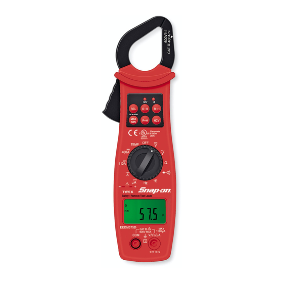
D. MEASUREMENT TECHNIQUES 1. Controls and Functions: Push Buttons Activates Relative mode. Press and hold for 2 seconds to deactivate. Zero Mode in 110A and 400A at DCA Funtion. Holds the reading on the display until the button is pushed a second time. Activates manual ranging. - Page 13 1. Controls and Functions: (cont.) Rotary Switch Turns the EEDM575D completely off. Used to measure DC volts. Used to measure AC volts. Used to measure resistance. Used to measure continuity. Selects diode test function. Selects capacitance test function. Selects frequency test function.
-
Page 14: Step By Step Procedures
4. Set rotary switch to the range. 5. Connect test leads to circuit to be measured. 6. Reconnect power to circuit to be measured. 7. Read the voltage on the EEDM575D. Optional Modes (See Other Features Section) • D-H: Freezes the reading on the LCD. - Page 15 4. Set rotary switch to the range. 5. Connect test leads to circuit to be measured. 6. Reconnect power to circuit to be measured. 7. Read the voltage on the EEDM575D. Optional Modes (See Other Features Section) • D-H: Freezes the reading on the LCD.
- Page 16 3. Plug red test lead into V/ input jack. 4. Set the rotary switch to the function. 5. Connect test leads to circuit to be measured. 6. Read the resistance value on the EEDM575D. Optional Modes (See Other Features Section) • D-H: Freezes the reading on the LCD.
- Page 17 Measuring AC Amperage CAUTION! Do not attempt to make a current measurement with the test leads. The EEDM575D measures the current by clamping the jaw around one conductor (wire). Clamping around more than one wire will result in erroneous readings. Make sure the temperature probe is NOT plugged in during this test.
- Page 18 Measuring DC Amperage CAUTION! Do not attempt to make a current measurement with the test leads. The EEDM575D measures the current by clamping the jaw around one conductor (wire). Clamping around more than one wire will result in erroneous readings. Make sure the temperature probe is NOT plugged in during this test.
- Page 19 4. Set the rotary switch to the position. 5. Connect test leads to circuit to be measured. 6. The EEDM575D will beep and the LED will illuminate at resistances of 35 W W or lower. Optional Modes (See Other Features Section) •...
- Page 20 Measuring Diodes WARNING! Do not attempt to make diode measurements with the circuit energized. For accurate tests, remove the diode completely from the circuit prior to measuring it. Make sure the temperature probe is NOT plugged in during this test. Instrument set-up: FUNC.
- Page 21 Measuring Capacitance WARNING! All capacitance measurements are to be made on de- energized circuits with all capacitors discharged only. Failure to de-energize and discharge capacitors prior to measuring them could result in instrument damage and/or personal injury. Make sure the temperature probe is NOT plugged in during this test.
- Page 22 Measuring Frequency WARNING! Never attempt a frequency measurement with a voltage source greater than 500V. Determine the voltage of any unknown frequency source before connecting the instrument in frequency mode. Make sure the tempera- ture probe is NOT plugged in during this test. Instrument set-up: FUNC.
- Page 23 V/W/mA 4. Set the rotary switch to the function. 5. Reconnect power to the circuit to be measured. 6. Read the frequency on the LCD. 7. Read the current on the EEDM575D. Optional Modes (See Other Features Section) • D-H: Freezes the reading on the LCD.
- Page 24 4. Touch the temperature probe to the item to be measured. 5. Read the temperature on the LCD. Note: The EEDM575D will beep when no probe is connected to the temperature input. Optional Modes (See Other Features Section) •...
-
Page 25: Other Features
3. Put the arrow marked on the jaw close to the wire under test. 4. If voltage is present the EEDM575D will beep and the NCV LED will illuminate. 5. If voltage is not detected, confirm the result by per- forming a voltage measurement as outlined earlier in this manual. - Page 26 REL mode. To clear or exit relative mode, press and hold the REL button for approximately two seconds and the EEDM575D will beep and return to nor- mal operation. Note: Differential temperature measurements can be made using relative mode. See the appli-...
- Page 27 MIN and the mini- mum reading recorded. Press the MAX/MIN button again and MAX MIN will blink and the EEDM575D will display the measured value in real time. Steps 2 and 3 can be repeated to read the maximum and minimum recorded values.
- Page 28 NOTE: Peak mode can display up to 70 counts on the display when first activated. For exam- ple, if the EEDM575D is set to the ACA func- tion and manually ranged to the 40A range, when P-H is activated the display can read up to 0.70.
- Page 29 LCD display. This function is useful when measuring in locations where the display is difficult to read. LED Indicators The EEDM575D is equipped with three LED indica- tors at the top near the jaw. This indicator illuminates when the non- contact voltage detector senses a voltage.
-
Page 30: Application Notes
F. Application Notes (AC Volts) Disconnect power from the terminal block, find the fuse or circuit breaker that controls the block and turn it off. steps under “ Measurement Set up the meter following the Procedure ” on page 15. Then proceed with the follow- ing: •... - Page 31 Application Notes (DC Volts) The EEDM575D will accurately measure rectified DC Voltages like those encountered in furnaces and other appliances even though many of these devices do not have output filtering or other signal condi- tioning. When measuring DC Voltage of a battery, the most accurate reading can be attained by testing the battery under load.
- Page 32 Application Notes (Resistance) When measuring resistance of a motor, make sure the power is disconnected prior to testing. Set up meter following steps under “ Measurement Procedure ” on page 16, and proceed with the fol- lowing: • Connect the red test lead to one power input line of the motor and the black test lead to the other power input line of the motor.
- Page 33 Application Notes (AC Amps) When measuring AC Amps of a motor there are two types of measurements that can be made, running current and in-rush or start-up current. Start-up current will usually be much higher than running current. “ Measurement Procedure ” on page 17, and Set up the meter following the steps under then proceed with the following: Clamp the meter around a single wire and...
- Page 34 • Remove the test leads from the input jacks. Insert the K-type thermocouple probe into the input jack on the EEDM575D. Set the EEDM575D to the desired TEMP function. • Touch the temperature probe sensor to the device under test (T1).
-
Page 35: Trouble Shooting Guide
G. Trouble Shooting Problem Probable Causes Does not power up • Dead or defective battery • Broken wire from battery snap to PCB Won’ t display DC • Open fuse microamp readings • Open test lead • Improperly connected to circuit under test All functions except •... -
Page 36: Maintenance
H. Maintenance 1. Battery / Fuse Replacement: The EEDM575D will display a battery symbol when the internal 9 Volt battery needs replacement. If DC microamps does not operate correctly the 0.5A / 600V fuse needs to be replaced. The battery or fuse is replaced as... -
Page 37: Accessories
I. Accessories ** These optional accessories have not been eval- uated by UL and are not considered as part of the UL Listing of this product. “ Individual protective device must be used if HAZARDOUS LIVE parts in the installation where measurement is to be carried out could be ACCESSIBLE”... - Page 38 EEDM575DZ User’ s Manual © 2011 Printed in Korea The information, specifications and illustrations in this manual are based on the latest information available at the time of printing. Snap-on Tools Company reserves the right to make changes at any time without notice.
Need help?
Do you have a question about the EEDM575D and is the answer not in the manual?
Questions and answers