Subscribe to Our Youtube Channel
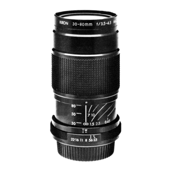
Summary of Contents for Kiron 30-80ММ F/3.5-4.5
- Page 1 Digitally signed by boggy boggy DN: cn=boggy, c=GB, email=himself@boggys.co.uk Date: 2018.10.17 10:05:01 +01'00'...
- Page 20 KIRON 30 – 80 F/3.5 – 4.5 PART PART DESCRIPTION QUANTITY NUMBER NUMBER K56001 800515 RING, NAME Z75905B 760520 SETSCREW, 1.4 x 1.5 K56002 800515 RING. FRONT Z75918B 760520 SETSCREW, 1.4 x 2.0 K56912 800515 RING, FABRIC A K56902 800515 SPACER, FRONT FOCUSING 1.0mm...
- Page 21 KIRON 30 – 80 F/3.5 – 4.5 PART PART DESCRIPTION QUANTITY NUMBER NUMBER Z75968B 760520 SCREW, FLATHEAD 1.4x3.0 K56017 801205 PLATE, DIAPHRAGM BLADE RETAINING W25938 760817 POST, DIAPHRAGM BLADE K56700 800515 BLADE DIAPHRAGM K56701 800515 RING, BLADE OPERATING K56900 800515...
- Page 22 KIRON 30 – 80 F/3.5 – 4.5 PART PART DESCRIPTION QUANTITY NUMBER NUMBER Z75934W 760520 SCREW, STOPPER K56021 800515 COVER, REAR K56713 800515 RING, BLADE OPERATING K56901 800515 SPRING, BLADE OPERATING K56712 800515 LEVER, DIAPHRAGM K56711 800515 RING, APERTURE CAM...
- Page 23 KIRON 30 – 80 F/3.5 – 4.5 PART PART DESCRIPTION QUANTITY NUMBER NUMBER K56041oB 800515 RING, APERTURE K24964 770720 WASHER, OLYMPUS MOUNT K24047 770720 RING, BALL RETAINER K56721 800515 LEVER, DIAPHRAGM ACTUATOR A Z71027 780710 RING, DIAPHRAGM ACTUATOR Z71905 780710...
- Page 24 KIRON 30 – 80 F/3.5 – 4.5 PART PART DESCRIPTION QUANTITY NUMBER NUMBER K56039PB 800515 RING, APERTURE K56717 800515 LEVER, CAM RING OPERATING V82757 790903 WASHER, PENTAX MOUNT K24753 770720 RING, APERTURE SIGNAL RING RETAINER K56045 800515 RING, APERTURE SIGNAL...
- Page 25 KIRON 30 – 80 F/3.5 – 4.5 PART PART DESCRIPTION QUANTITY NUMBER NUMBER K56N81N 801223 LENS, 1 GROUP K56N82N 801223 LENS, 2 GROUP K56N41N 800928 HELICOID ASSEMBLY K56N31N 800928 DIAPHRAGM HOUSING ASSEMBLY K56N83N 801223 LENS, 3 GROUP K56N84N 801223 LENS, 4...
- Page 26 DISASSEMBLY AND REASSEMBLY OF 30-80mm f3.5-4.5 (M/MD-MOUNT) DISSASEMBLY Loosen one setscrew (2) and unscrew the Name Ring (1). Loosen one setscrew (4) and unscrew the Front Ring (3). Unscrew the 1st Lens Group (501) and remove the Front Focusing Spacers (6). Unscrew the 2nd Lens Group, using tool #R56001/K56025.
- Page 27 1.15 Loosen two setscrews (48) on the Helicoid Stopper Ring (47). Unscrew the Helicoid Stopper Ring together with the Focusing Limit Ring (51). 1.16 Remove two panhead screws (35) and two flathead screws (36), and remove the 3rd Lens Group Ring (45). 1.17 Remove three sets of Roller Shaft (43), Roller A (42), Roller B (41), and Washer (10).
- Page 28 REASSEMBLY HELICOID ASSEMBLY (503) Drop the Diaphragm Housing Assembly (527M) in place in the Inner Helicoid (44), and replace the three screws (53). When correctly inserted, the Diaphragm Lever (109M) on the Diaphragm Housing Assembly will align with the notch on the front rim of the Inner Helicoid.
- Page 29 Insert the 3rd Lens Group Ring (45) in the Inner Helicoid (44) with the internal threads towards the rear of the lens, and replace the two flathead screws (36) and the two panhead screws (35). The correct orientation of the 3rd Lens Group Ring with respect to the Cam Ring (34), and the respective locations of the flathead screws and the panhead screws, are indicated in Figure 4.
- Page 30 The drawing shows the relative positions of the 3rd Lens Group Ring (45) and the two Helicoid Plates (49 and 52) with respect to the Inner Helicoid (44) and the Cam Ring (34). "Up" in the drawing is defined by the tab on the Helicoid Stopper Ring (47) when the lens is set at infinity, as shown in the top section of the drawing.
- Page 31 Turn the Outer Helicoid (46) all the way to the infinity stop (see Figure 5). The distance A, from the shoulder on the Focusing Limit Ring (51) to the rear rim of the Inner Helicoid (44), shall now be 10mm, and the distance B, between the front rim of the Outer Helicoid (46) and the ridge on the front rim of the Cam Ring (34), shall be 1mm, as shown in Figure 5.
- Page 32 2.10 Insert the Focal Length Indicator Ring (15) and slide it forward under the Zoom Drive Ring (9). (Do NOT replace the screws (16)). 2.11 Replace the 3rd Lens Group (505), using tool R56002/K56026. 2.12 Replace the 4th Lens Group (506). 2.13 Drop the Rear Mount Assembly (528M) in place, making sure the coupling levers engage correctly.
- Page 33 DIAPHRAGM ADJUSTMENT 2.17 Set the lens to minimum aperture (f/16 at the W-index). Loosen the three screws (53), which hold the Diaphragm Housing Assembly (527M) to the Inner Helicoid (44), and rotate the Diaphragm Housing Assembly until the width of the iris aperture is 3.0mm, when measured as indicated in Figure 6.


Need help?
Do you have a question about the 30-80ММ F/3.5-4.5 and is the answer not in the manual?
Questions and answers