Advertisement
Quick Links
Advertisement

Summary of Contents for KENT USA KTM-5VKF-E
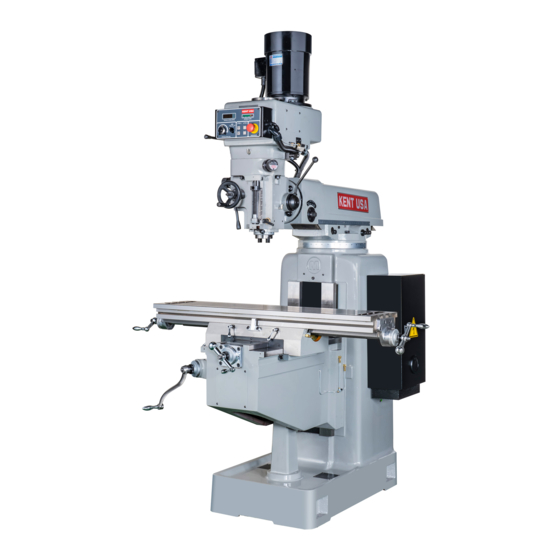
- Page 1 KTM-5VKF-E Manual Knee Mill Operation Manual www.kentusa.com 1.800.KENT.USA...
- Page 3 -- Jl - - � - ---· ..rt MIN. 2¼'_' (5Z) � ; J Ml::.1�.-(�\� � 57" (1 4 5 0) Fi!?,1.JrC'. 1. Basic Dim<'nsions...
- Page 6 UNCRATING: Carefully remove protective crating so machine and parts are not marred or damaged. In the event of damage in transit, IMMEDIATELY notify the distributor from whom the machine was purchased, as well as the transportation company making delivery. CLEANING: Thoroughly clean protective coating from machine with suitab�e cleaning solution.
-
Page 7: Lifting The Machine
LIFTING THE MACHINE Note position of ram and table when lifting with sling • PROPER LIFTING SLING (4) BOLTS TIGHTEN TO 75FT. LBS. TORQUE BEFORE LIFTING TIGHTEN RAM LOCKING BOLTS BEFORE LIFTING MOVE TABLE AGAINST COLUMN □ INSTALLED GROSS WEIGHT OF MACHINE APPROX. - Page 9 40¾" (1035) � I-• � .._ i == = L�------ J J (�l{J\ -)· ...__- -,--- -- ----- - -- - " 78" (1981) - -- -- •-·- -- -- ----- -- ---- • FIGURE 3 INSTALLATION LAYOUT -8 -...
- Page 10 ALIGNMENT OF HEAD: In case of precision work where it is necessary to have head perfectly spuare wuth the table, use method described below. To set head square with table, see Figures 4. Loonsen four locknets (143#,page 34).but leave longitudinal axis.mount indicator as shown in Figure 4. LOCKNUTS Figure 4.
-
Page 11: Adjustment Of Saddle Gib
GIB ADJUSTING SCREW ADJUSTMENT OF TABLE GIB. table is provided with a full length tapered gib_ (#6 3 , page 24)1 in the saddle, and an adjusting screw on the left side. To take up gib, tighten gib adjusting screw (#43, page 24)) slightly and repeat until a slight drag is felt when moving the table by hand. - Page 13 REMPVING TABLE: RemovP. the following: ball crank, handles, dial holders and bearing brackets. Tum the lead screw all the way out and slide the table from the saddle. See Fig. 8. REMOVING SADDLE: Follow the same procedures as removing table; however, it is necessary to remove the entire front bracket assembly.
- Page 14 LEFT BEAHING BRACKl:.' 1 ' oRACKE' t FEED SCREW "'"" LONGITUDINAL (#'25 P.28) JdyJ'ftl ..-===;;;;;;1 �--- BEARING .;EALl::D BALL REARING (#9,P2 8) LONG & CROSS FEED NUT ..(#20,P28) .' / / CROSS FtED BEARING B1-:ACKE'f (#15,1'28) .·# / moss FEED SCREW ADJllSTING (#13,P28)
- Page 16 MOTOR For-Rev Range Switch (Mounted on R.F. Side of Head) SPEED CHANGE HANDWHEEL 15 HI-NU HI-NEUTRAL-LO 4 POWER FEED LEVER TRANSMISSION ENGAGEMENT CRANK. QUILL FEED HANDLE 1 4 QUILL STOP KNOB - - - - - - -al 6 MANUAL FEED HANDWHEEL 12 QUILL LOC K 7 FEED REVERSING...
-
Page 19: Feed Control
NOT E The feeq control lever must be engaged in order to use manual feed controls. The Quill Feed Handle and Manual Feed Handwheel may be taken off when not in use. FEED CONTROL Engages· LEVER (#8, Fig. 9): over-load clutch on pinion shaft when m o ved left and will stay engaged until either quill stop comes in contact with micrometer Rdj usting forcing feed control lever to disengage automatically, or release d ·... - Page 20 RAM POSITION R· am can bt: movt:d by loosening two ram lock studs (#21, p age 24) on turret (#11, page 24) and moving to desired position. CAUTION CARE SHOULD BE TAKEN TO LOCK RA!\l SECURELY AFTER SETTING. NOTE It is recommended· t. h at �n heavy milling work, head should be kept as close to col umn as possible, where maximum rigidity is obtained.
- Page 23 CHANGING VARI-DRIVE BELT (Figure 11) Complete the procedures for removing the motor, then remove the previous and lift out the top bearin g · cap three screws (A. Fig. 11 ) (#1, page 36) (B). Looking down inside of the housing, locate and re (#1 3, pa g e 3 4 ) m ov e two socket he .
- Page 25 5K / 5VK / 5VKF BASIC MACHINE -24-...
- Page 26 5K / 5VK / 5VKF BASIC MACHINE ITEM NO. PARTS NO. DESCRIPTION ITEM NO. PARTS NO. DESCRIPTION 5K-5040 Worm Shaft 4H-3027 Saddle/Knee Gib 5K-5039 Worm 3035 Table Stop Bracket 5K-5040-1 Adj.Bushing (1SET) 001-I0300060 Socket Cap Screw(3/8"*3/4")(2Req) (3036) 5A-5043 Head Swivel Plate 5K-3032 Saddle Lock Plunger 5A-5006...
- Page 27 10"x50" / 10"x45" TABLE -26-...
- Page 28 10"x50" / 10"x45" TABLE ITEM NO. PARTS NO. DESCRIPTION 2016 Dial Lock Nut (3Req) 2012-I Dial With 200 Graduations (3Req) (INCH TYPE) 2012-M Dial With 250 Graduations (3Req) (M/M TYPE) 2014 Dial Holder (3Req) 020-006204ZZ Grease Seal Ball Bearing(6204ZZ#) (5Req) (2008) 2006 Bearing Bracket (2Req)
- Page 29 5K HEAD TOP HOUSING 5K HEAD TOP HOUSING ITEM NO. PARTS NO. DESCRIPTION ITEM NO. PARTS NO. DESCRIPTION 009-I0000040 Nut(1/2") (5K-8070-1) 5K-7080 Gear Shaft 5K-8074 Brake Lock Shaft 013-06060020 Key(6*6*20) (2Req) (5K-7078) 001-M0600020 Socket Head Cap Screw(M6*20) (5K-8072) 036-00000010 Grease Nipple(PT1/8") (5K-8063-1) 008-M0600006 Set Screw(M6*6) (4Req)
-
Page 30: Head Top Housing
5K HEAD TOP HOUSING ITEM NO. PARTS NO. DESCRIPTION ITEM NO. PARTS NO. DESCRIPTION 009-I0000040 5K-7080 Nut(1/2") (5K-8070-1) Gear Shaft 5K-8074 013-06060020 Brake Lock Shaft Key(6*6*20) (2Req) (5K-7078) 001-M0600020 Socket Head Cap Screw(M6*20) (5K-8072) 036-00000010 Grease Nipple(PT1/8") (5K-8063-1) 008-M0600006 Set Screw(M6*6) (4Req) (5K-7077) 001-M1000020 Socket Cap Screw(M10*20)(6Req) - Page 31 NT40# SPINDLE HEAD PART A -30-...
- Page 32 NT40# SPINDLE HEAD PART A ITEM NO. PARTS NO. DESCRIPTION ITEM NO. PARTS NO. DESCRIPTION 001-M0600050 Socket Cap Screw(M6*50)(2Req) (5K-6206) 6173 Black Plastic Ball Handles(3/8") 026-0000HP25 Plastic Plug(HP25) (5K-6205-1) 009-I0000040 Nut(1/2") (5K-6174-1) 6202 Clutch Ring Pin (2Req) 5K-6178 Rack Feed Handle Hub 016-P0600020 Pin(6*20) (5K-6204)
- Page 33 NT40# SPINDLE HEAD PART B -32-...
- Page 34 NT40# SPINDLE HEAD PART B ITEM NO. PARTS NO. DESCRIPTION ITEM NO. PARTS NO. DESCRIPTION 027-00000150 Steel Ball(3/16") (6255) 006-M0400005 Chem Blacked RD.HD.Screw(M4*5) (4Req) 5K-6219-2 Compression Spring 5K-6116 Quill Lock Sleele Guard 5K-6219-1 Hand Wheel Clutch Spring Screw 5K-6117 Quill Lock Bolt Spacer 3H-7069 Plastic Handle (2Req) 5K-6242...
- Page 35 5VK / 5BVK / TW-40 VARI-SPEED HEAD TOP HOUSING -34-...
- Page 36 5VK / 5BVK / TW-40 VARI-SPEED HEAD TOP HOUSING ITEM NO. PARTS NO. DESCRIPTION ITEM NO. PARTS NO. DESCRIPTION 010-M0000010 Hex Cap Nut(M10) (5K-7001) 5K-7071 Hi-Low Pinion Block 001-M0600050 Socket Cap Screw(M6*50)(4Req) (5K-7025) 001-M0500006 Socket Head Cap Screw(M5*6) (7064) 008-M0600016 Set Screw(M6*16) (5K-7004) 001-M0400020...
- Page 37 5VK / 5BVK / TW-40 VARI-SPEED HEAD BACK GEAR -36-...
- Page 38 5VK / 5BVK / TW-40 VARI-SPEED HEAD BACK GEAR ITEM NO. PARTS NO. DESCRIPTION ITEM NO. PARTS NO. DESCRIPTION 001-M0800020 Socket Cap Screw(M8*20) (3Req) (5K-8001) 5K-8068 Brake Operating Finger 5K-7013 Top Bearing Cap 5K-8068-1 Washer 009-M0000010 Nut(M10) (5K-8007) 5K-8067 Brake Finger Pivot Stud (2Req) 020-06209LLB Ball Bearing(6209LLB#) (5K-8004)
- Page 39 5VKF TW-40QI HEAD TOP HOUSING OF INVERTER MOTOR TYPE 103 104 -38-...
- Page 40 5VKF TW-40QI HEAD TOP HOUSING OF INVERTER MOTOR TYPE ITEM NO PARTS NO. DESCRIPTION ITEM NO PARTS NO. DESCRIPTION 7005I-2 Pendant Plate 008-M0600006 Set Screw(M6*6) (2Req) (5K-8076) 7005I-2-K Pendant Plate 001-M1000030 Socket Cap Screw(M10*30)(6Req) (5K-8064) 006-M0400005 Chen Blocked RD.HD Screw(M4*5) (4Req) 016-T0500040 Taper Pin (2Req) (5K-8060)
- Page 41 5-GL HEAD TOP HOUSING -40-...
- Page 42 5-GL HEAD TOP HOUSING ITEM NO. PARTS NO. DESCRIPTION TRH-6009A(5GT-37T) Low Speed Motor Timing Pulley TRH-6009B(5GT-55T) Hi Speed Motor Timing Pulley TRH-6009C Washer TRH-6009D Timing Pulley Clutch Sleeve 013-08070030 Key(8*7*30) 001-M0500010 Socket Head Cap Screw(M5*10)(4Req) 5K-6013F Belt Housing 020-06010LLB Bearing(6010LLB#) (2Req) TRH-8053-1 Bearing Retainer Ring TRH-8034...
- Page 43 5RG HEAD TOP HOUSING OF INVERTER MOTOR TYPE -42-...
- Page 44 5RG HEAD TOP HOUSING OF INVERTER MOTOR TYPE ITEM NO. PARTS NO. DESCRIPTION ITEM NO. PARTS NO. DESCRIPTION 006-M0400005 Chen Blocked RD.HD.Screw(M4*5) (4Req) 020-006204ZZ Ball Bearing(6204ZZ#) (2Req) (5K-7079) 3F-7005 Pendant Plate 5K-7083 Bull Gear Pinion 003-M0400010 Socket Head Cap Screw(M4*10) (4Req) 3B-7071-1 Limit Switch Bracket Name Plate...
- Page 45 CENTRAL LUBRICATING OIL EQUIPMENT(4VK/5VK) 數量 ITEM NO. PARTS NO. DESCRIPTION 028-CLA-08-L (9001) Hand Oiler 028-000AT-05 (9003) "A" Type Distributor-A5 028-000PKD-4 (9007) 3-Way Junction (PKD-4) Aluminium Pipe 028-AL-PI-04 (9002) 028-000AT-08 "A" Type Distributor-A8 028-0000CPS2 Ratio Distributor Controller-CPS2 (4Req) 028-0000CPS3 Ratio Distributor Controller-CPS3 (2Req) 028-0000CPS4 Ratio Distributor Controller-CPS4 (2Req) 028-0000CPS5...
Need help?
Do you have a question about the KTM-5VKF-E and is the answer not in the manual?
Questions and answers
the quill feed control shift lever will not stay engaged. Is there some detent spring that can be adjusted? I desperately need this machine to bore a part that is setup and waiting.
The KENT USA KTM-5VKF-E manual does not provide specific instructions on adjusting the detent spring for the quill feed control shift lever. However, if the detent spring is not keeping the lever engaged, you may try the following general steps:
1. Locate the Detent Spring – Identify the detent spring and related components in the quill feed control mechanism.
2. Check for Wear or Damage – Inspect the spring for wear, deformation, or damage.
3. Adjust Spring Tension – If possible, increase the spring tension by repositioning it or replacing it with a stronger spring.
4. Secure Fasteners – Ensure that all screws, pins, and related components are tight and properly aligned.
5. Lubricate Moving Parts – Apply light lubrication to reduce friction and improve engagement.
If further adjustment is needed, refer to the machine’s service manual or consult a technician.
This answer is automatically generated