Table of Contents
Advertisement
Quick Links
Flavor Burst
®
Flavor Dispensing System
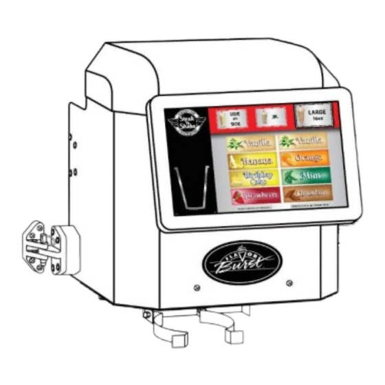
Model CTP 80SNS-R
Model CTP 80SNS-L
Equipment, Maintenance and
Operations Manual
Manufactured by
Flavor Burst Company
499 Commerce Drive
Danville, IN 46122
For general information and to locate a
distributor near you, call or visit our website:
Phone: (317) 745-2952
Toll Free Number: (800) 264-3528
Fax: (317) 745-2377
www.flavorburst.com
For pricing, ordering and support,
contact one of our qualified distributors.
NOTE: THIS SYSTEM USES XXX SYRUPS ONLY (xxx)
NOT compatible with the standard Flavor Burst syrups. To reorder syrups, contact......
Warranty
An installation and warranty form is provided with every Flavor Burst system, located inside the SNS
series unit with this manual. It is important that the operator carefully review the warranty and installation
documents accompanying the unit before using this system. Any questions or concerns regarding the
warranty should be clarified upon delivery or installation. For more information, contact your local
authorized Flavor Burst
©2021 Flavor Burst Company
All Rights Reserved
®
distributor.
Printed in January
This system is
Printed in
The United States of America
Advertisement
Table of Contents

Summary of Contents for Flavor Burst CTP 80SNS-R
- Page 1 NOT compatible with the standard Flavor Burst syrups. To reorder syrups, contact..Warranty An installation and warranty form is provided with every Flavor Burst system, located inside the SNS series unit with this manual. It is important that the operator carefully review the warranty and installation documents accompanying the unit before using this system.
-
Page 2: Table Of Contents
TABLE OF CONTENTS FCC ID……………………………...………………………………………….………………...3 Introduction……………………………...………………………………………….………….4 Safety Precautions……………………………..…………….………..……..….…………..4 Environmental Notices………………...………………………………………….………….6 Parts Identification/Function……...……………………….……..…..……….……..….…..7 Daily Opening Procedures……..………………………….…….…..…….………..……...26 Cup Holder and Base Panel…………………………..….………………..…...…26 Daily Closing Procedures………………………………………….……………….……….28 Cup Holder and Base Panel…………………………..….………………..…...…28 Door Assembly Interior......………………..……………………….……29 Other External Parts....…………………………………..……………...…..30 Cup Holder and Base Panel…………………………..….………………..…...…30 Replacing the Syrup Flavors…………...…………………………..…….………...……...32 Scheduled Maintenance…………...……………………………….…….………...…...….36 Clean-In-Place Procedure……………………………..……..…………..…...36 Miscellaneous Cleaning Procedures………………………………….………..…43... - Page 3 TABLE OF CONTENTS (continued) Equipment Setup……………………………………………………...…..……….……..….46 Installing the Door Assembly.........……………………..…46 Right Side Door Assembly Installation.........………...46 Left Side Door Assembly Installation....….……………………...…47 Installing the Cup Holder Arm Support..……………………….………...…………..48 Connecting the Draw Switch ..………………………………….………...…………..49 Right Side Switch Connection............………...49 Left Side Switch Jack Installation.......….……………………...…49 Installing the Tube and Cable Rail……………………………….…...…………...…50 Right Side Rail Installation............………...50 Left Side Rail Installation........….……………………...…51...
-
Page 4: Fcc Id
FCC Conformity Statement This device complies with Part 15 of the FCC Rules. Operation is subject to the following two conditions: (1) this device may not cause harmful interference, and (2) this device must accept any interference received, including interference that may cause undesired operation. Changes or modifications not expressly approved by the party responsible for compliance could void the user's authority to operate the equipment. -
Page 5: Introduction
24 hours, follow the DAILY OPENING PROCEDURES. Operate unit under normal ambient The CTP 80SNS-R system attaches to the right temperatures between 60 and 80 degrees side of the freezer, while the CTP 80SNS-L is Fahrenheit. Unit should never be exposed to designed to attach to the left side. -
Page 6: Environmental Notices
Fahrenheit. Unit should never be change. Contact your local distributor for most exposed to freezing temperatures. recent updates concerning the Flavor Burst unit. ENVIRONMENTAL NOTICES If the crossed out wheeled bin symbol is affixed to this product, it signifies that this product is compliant with the EU Directive for Waste Electric/Electronic Goods (WEEE) as well as other similar legislation in affect after August 13, 2005. - Page 7 PAGE INTENTIONALLY LEFT BLANK...
-
Page 8: Parts Identification/Function
QTY. FUNCTION TOUCH PANEL DOOR RIGHT ASSEMBLY INSTALL: Right side FAC 900R ASSEMBLY – SNS SYSTEM – Flavor Burst SNS unit command center. RIGHT SIDE TOUCH PANEL DOOR LEFT ASSEMBLY INSTALL: Left side FAC 900L ASSEMBLY – SNS SYSTEM –... - Page 9 General System Overview Figure 1...
- Page 10 Cabinet – (See Figure 2) ITEM PART NO. DESCRIPTION QTY. FUNCTION ELECTRONICS SYSTEM Control system for the unit. CAB 135R-SNS RIGHT SIDE PANEL - SNS Right outer wall of the cabinet. CAB 145 TRAY SUPPORT BRACKET Supports trays and flavor / sanitizer tubes. FAS 2024 8-32 X 1/4 PAN HEAD Attaches various panels of the cabinet.
- Page 11 Cabinet (Continued) ITEM PART NO. DESCRIPTION QTY. FUNCTION FAS 2035 8-32 NUTS - EXT. LOCK WASHER Attaches screw and secures rubber bumper. MIS 3074 SHORTY PLUG #1672 Covers screw hole in rubber bumper. FAS 2040 6-32 X 1/4" TAPPING SCREW 24 Secures tray support bracket to side panels.
- Page 12 MIS 3525L SNS FACADE FACE LEFT panel of “left” Door Assembly. ELE 906SNS F10 DRIVER BOARD CTP - SNS Flavor Burst unit command center. MIS 3526 FACADE CTP MOUNT SNS Mounts Touch Panel to front of Door panel. MIS 3150 FLAVOR BURST LOGO DECAL Displays Flavor Burst trademark logo.
- Page 13 Door Facade Assembly – Exterior Features (Continued) ITEM PART NO. DESCRIPTION QTY. FUNCTION 10-32 x 5/8 TRUSS PHILLIPS MS Secures the receiving latch part to the FAS 2135 freezer. SCREW Secures the Door’s latch to the Door FAS 2191 10-32 x 1" PHILLIPS PH S.S. SCREW Assembly.
- Page 14 PAGE INTENTIONALLY LEFT BLANK...
- Page 15 Door Facade Assembly – Exterior Features Figure 3A...
- Page 16 Door Facade Assembly – Interior Features (See Figure 3B) ITEM PART NO. DESCRIPTION QTY. FUNCTION EXTERNAL DOOR ASSEMBLY See Figure 3A FEATURES CUP HOLDER ASSEMBLY RIGHT - RIGHT ASSEMBLY INSTALL: Holds serving MIS 3520-R cup and funnel under spout. MIS 3520A CUP HOLDER FRAME SNS 1 ea.
- Page 17 Door Facade Assembly – Interior Features (Continued) ITEM PART NO. DESCRIPTION QTY. FUNCTION FAS 2136 10-32 TWO PIECE HEX CAPNUTS Covers the ends of the screws. 10-32 x 1 1/4 PHILLIPS PH S.S. FAS 2192 Attaches the spacers to the weight sensor. SCREW Allows for space between the middle and FAS 2188...
- Page 18 ITEM PART NO. DESCRIPTION QTY. FUNCTION Secures the thumbscrew of the lift bracket to FAS 2067 1/4" PLASTIC WASHER freezer draw bracket. Secures the thumbscrew of the lift bracket to RUB 673 00 FLAT WASHER ½” OD freezer draw bracket.
- Page 19 Door Facade Assembly – Interior Features Figure 3B...
- Page 20 Syrup Pump and Related Parts (See Figure 4) ITEM PART NO. DESCRIPTION QTY. FUNCTION SOFT SERVE SYRUP PUMP Pumps syrup from flavor bags to flavor lines. ASSEMBLY SYR 926-SNS SOFT SERVE SYRUP PUMP 1 ea. Pumps syrup from flavor bags to flavor lines. 1/4"ID SHAKE PUMP REPL.
- Page 21 Syrup Pump and Related Parts Figure 4...
- Page 22 Sanitizer Pump and Related Parts (See Figure 5) ITEM PART NO. DESCRIPTION QTY. FUNCTION Collects and carries discarded syrup and MIS 3533A* SNS FUNNEL ASSEMBLY sanitizer solution from cupholder to a bin. Collects and carries discarded syrup and MIS 3533* SNS EXTENDED FUNNEL 1 ea.
- Page 23 Sanitizer Pump and Related Parts (Continued) ITEM PART NO. DESCRIPTION QTY. FUNCTION LEFT ASSEMBLY INSTALL: Supplies TUB 803 .17 x 1/4 LDPE TUBING sanitizer from Sanitizer Tank. LEFT ASSEMBLY INSTALL: Connects FIX 1053 SANITIZER SUPPLY TUBING sanitizer tube to supply tube. NOTE: Not included with FAC 900L “left”...
- Page 24 8-32 X 1/2" PAN HEAD Secures various parts within the top of unit. MIS 3150 FLAVOR BURST LOGO DECALS Displays Flavor Burst trademark logo. CAB 156 CONNECTOR SHIELD Protects power cables from liquids. Provides a power connection to the outside ELE 485CTP 120V POWER ENTRANCE MODULE of the cabinet.
- Page 25 Electronic Parts and Connections Figure 6...
- Page 26 PAGE INTENTIONALLY LEFT BLANK...
-
Page 27: Daily Opening Procedures
3. Remove the parts from the sanitizer DAILY OPENING PROCEDURES solution. Place the items on a sanitary tray to air dry. NOTE: YOUR HANDS SHOULD BE CLEANED AND SANITIZED BEFORE YOU PERFORM THE FOLLOWING PROCEDURES. NOTE: THE FOLLOWING PROCEDURES REQUIRE APPROVED, SERVICEABLE AND SANITIZED TOOLS AND BRUSHES. - Page 28 PAGE INTENTIONALLY LEFT BLANK...
-
Page 29: Daily Closing Procedures
4. Remove the thumb screws and base panel DAILY CLOSING PROCEDURES of the Door Assembly. NOTE: YOUR HANDS SHOULD BE CLEANED AND SANITIZED BEFORE YOU PERFORM THE FOLLOWING PROCEDURES. NOTE: THE FOLLOWING PROCEDURES REQUIRE APPROVED, SERVICEABLE AND SANITIZED TOOLS AND BRUSHES. CONTACT YOUR LOCAL DISTRIBUTOR FOR RECOMMENDED SUPPLIES. -
Page 30: Door Assembly Interior
Door Assembly Interior 5. Spray sanitizer solution onto the draw spout. Allow the spout to sanitize for at 1. Remove the Door Assembly lid. least one minute. 2. Inside the Door Assembly, back out the draw bracket thumbscrew enough so that 6. -
Page 31: Other External Parts
8. Inspect the inside of the Door Assembly. Other Exterior Parts Check for leaks and other areas that may need to be spot-cleaned. 1. Inspect the flavor lines as they exit the façade and enter to the tubing rail. Clean, rinse and dry with detergent water, warm water, and single service towels when necessary. - Page 32 PAGE INTENTIONALLY LEFT BLANK...
-
Page 33: Replacing The Syrup Flavors
1. If there is a message on one or more of the REPLACING THE SYRUP FLAVORS flavors on your product screen that says “Syrup Container Empty”, or to view all NOTE: YOUR HANDS SHOULD BE CLEANED syrup levels, press and hold the logo in the AND SANITIZED BEFORE YOU PERFORM upper left corner to access the Maintenance THE FOLLOWING PROCEDURE. - Page 34 3. The empty flavor will show a red status bar 6. Remove the tray with the empty bag from and low percentage remaining. Touch the the cabinet. CHANGE SYRUP button for this flavor. If any bags show near empty, consult with a store supervisor or manager to decide if the flavor should be replaced.
- Page 35 10. Connect the syrup bag connector to the 13. Once replaced, the flavor will show 100%. syrup bag. 11. Go back to the screen, and press NEXT. 12. The following screen asks to confirm whether or not the syrup bag has been replaced with a new bag.
- Page 36 PAGE INTENTIONALLY LEFT BLANK...
-
Page 37: Scheduled Maintenance
This step-by-step guide will take you through SCHEDULED MAINTENANCE the necessary cleaning procedures for one flavor or all 8 flavors and the relevant parts. The following procedures are performed less The cleaning process takes approximately 20- frequently than daily or as needed. Use these 30 minutes, depending on whether you are instructions along with any cleaning / cleaning one line or all 8. - Page 38 4. Touch and hold the logo in the upper left 8. Prepare detergent water by mixing several corner of the Touch Panel until the drops of Dawn dish soap with a gallon of ® Maintenance Menu appears. warm water (108°F / 42°C). 9.
- Page 39 12. Connect the large end of the flush adapter 15. Place the funnel into the cup holder, under assembly to the syrup bag connector. the spout. Place the end of the funnel tube Twist until the connection is secure. Insert into a bucket.
- Page 40 17. Once all the lines have flushed, disconnect 20. With the funnel still under the spout, prime all the flush adapters. the cleaned syrup lines by pressing START. This only takes a few moments for each syrup line and then the process is complete. 18.
- Page 41 3. Steps 21-39 involve the Daily Closing 8. Remove the parts from the sanitizer solution Procedures. If performing the Clean-In- and place them on a sanitary tray to dry. Place Procedure at the end of the day, follow these steps now in place of the Daily Closing Procedures.
- Page 42 12. Brush and clean the draw spout and freezer 15. Use a single service towel moistened with panel behind the spout with warm detergent sanitizer solution to sanitize the spout metal water. Rinse with warm water and a single drip shield. Allow the metal drip shield to service towel.
- Page 43 18. Use the pin to secure the Door Assembly in 22. Then return the base panel and the cup the closed position. holder to the Door Assembly. 19. Reinstall the Door Assembly lid. 23. Remove the tank’s hand pump and discard any remaining sanitizer solution.
-
Page 44: Miscellaneous Cleaning Procedures
Miscellaneous Cleaning Procedures Inside of the Cabinet The following parts of the Flavor Burst system do not require daily cleaning. Inspect these areas periodically and clean if necessary according to instructions. Prepare detergent water by mixing several drops of Dawn® dish soap with a gallon of warm water (108°F / 42°C). -
Page 45: Touch Panel And Door Assembly
Touch Panel and Door Assembly NOTE: DO NOT GET WATER NEAR THE CABLE CONNECTIONS OR SPEAKER HOLES ON THE TOUCH PANEL. NOTE: DO NOT USE ANY HARSH CHEMICAL CLEANERS, BLEACH, AMMONIA, EXCESS WATER, BRUSHES OR ABRASIVE TOOLS TO CLEAN THE SURFACE OF THE TOUCH PANEL. - Page 46 PAGE INTENTIONALLY LEFT BLANK...
-
Page 47: Equipment Setup
Installing the Door Assembly EQUIPMENT SETUP The Door Assembly houses the dispensing NOTE: YOUR HANDS SHOULD BE CLEANED tubes, auto draw lift system, the weight sensor AND SANITIZED BEFORE YOU PERFORM system and the Touch Panel. Normal THE FOLLOWING PROCEDURES. operating functions are performed using the Touch Panel, including selecting sizes, flavors, NOTE: INSPECT ALL WEAR ITEMS AND... -
Page 48: Left Side Door Assembly Installation
3. With one person holding the Door Assembly 6. With one person holding the Door Assembly in place while a second person installs, in place while a second person installs, mount the latch assembly in between the mount the hinges of the Assembly to the two freezer doors. -
Page 49: Installing The Cup Holder Arm Support
9. Use the 4 self-tap screws to secure the 2. Use the two long screws to secure the latch assembly to the freezer panel. support arm to the weight sensor. Screw them into the sensor all the way, with the ends coming up through the top of the sensor. -
Page 50: Connecting The Draw Switch
When the draw spout is activated, the spigot sided Door Assembly to the freezer using the switch relays the signal to the Flavor Burst ® draw switch. Unlike the right side, which system, telling it to activate the pumps and already has an integrated switch jack installed, syrups as product is drawn from the spout. -
Page 51: Installing The Tube And Cable Rail
9. Unscrew the locking ring from the switch Installing the Tube and Cable Rail jack. Install the threaded post of the jack through the base panel opening. Secure the The syrup tubes and electrical cables that exit jack using the locking ring from the the Door Assembly are protected and held into underside of the base panel. -
Page 52: Left Side Rail Installation
3. Install the rail cover over the tubes and Left Side Rail Installation: Follow these cables using the screws provided. instructions to mount the Tube and Cable Rail to the left side of the freezer. Unlike the right side, which is pre-drilled and includes screws with the freezer, the left side of the freezer requires drilling some 3/16”... -
Page 53: Aligning And Adjusting The Cup Holder
8. Use the 3 self-tap screws provided to 2. Loosen the two nuts at the back of the cup secure the rail to the freezer panel. holder to adjust it from side to side. Loosen the two nuts on top of the weight sensor AND loosen the screws under the sensor to adjust the cup holder forward and backward. -
Page 54: Connecting The Auto Draw Lift And Closing The Door Assembly
Door Assembly lift bracket behind the freezer’s draw bracket and line up the screw hole with the thumb The Flavor Burst system is operated by the screw post. The thumbscrew’s washers Touch Panel, from selecting the flavor, serving and retainer rings should provide space size, and even drawing product. -
Page 55: Connecting The Sanitizer Tank
6. Install the Door Assembly lid to complete 1. Connect the sanitizer tube to the fitment on the closed position. The lid does not lock the Sanitizer Tank. into place, but it should sit over the top ledge of the Door Assembly frame so that it presses the internal switch bar down. -
Page 56: Power Connections And Power Up
Power Connections and Power Up 4. Connect the power cord to the port on the back panel. The electrical connections for the Flavor Burst system are located on the upper back panel of the unit. Once the cables have been connected and the unit is turned on, it can remain on during normal daily operations. -
Page 57: Installing The Syrups
Installing the Syrups 3. Place the bag into the tray and ensure the bag fitment is accessible through the tray The Flavor Burst system must have specific slot. flavors for each tray so that they match the flavor menu on the Touch Panel screen. Install... - Page 58 PAGE INTENTIONALLY LEFT BLANK...
-
Page 59: Touch Panel Setup
Accessing the Maintenance Menu program to communicate with the system and operate correctly. Other features, such as When first powering up the Flavor Burst SNS bounce sensitivity, can be adjusted as needed system, a “Calibration Due” message will later on. - Page 60 3. Leave the two “Automatic” settings 8. After the screen reboots, access the deactivated. These require constant wifi. Maintenance Menu again, and then click through the Equipment Setup Wizard, and Change Time screens. Touch the “Set time” key. 9. Touch the hour number of the time shown in the left side of the box, and move the hand on the clock face to the current hour.
-
Page 61: Cup Bounce Sensitivity
12. Leave the “use 24-hour format” deactivated 15. Cup Bounce Sensitivity As a failsafe, the in most cases. system detects when there is a reduction in weight from the cup holder while the ice cream is being dispensed. If a significant drop in weight is detected, the cup has likely fallen from the holder. -
Page 62: Change Switch Input
CHANGE SWITCH INPUT button to detect or fresh syrup. This is done when first setting the switch’s port. By default, Wired Switch up the Flavor Burst system with all new syrups, Port 1 is selected. Press ACCEPT. and sometimes when switching flavors and after the syrup line has been flushed with sanitizer solution. -
Page 63: Calibrating The System
Calibrating the System start to pump through the line and shut off automatically after 30 seconds. In order for the Flavor Burst system to dispense properly, you must calibrate a few sensors in If you need to stop the prime function early, this section. - Page 64 Door Assembly, and secure with the locking pin. 8. Reinstall the Door Assembly lid. 4. The Flavor Burst Door Assembly comes with a weight stored inside the Door Assembly. Remove the Door Assembly lid. 5. Remove locking pin and disconnect the Auto Draw Lift bracket.
-
Page 65: Ice Cream Dispense Calibration
Chocolate, will dispense longer than others due to the thickness. Therefore, each syrup flavor will have different settings. When first installing the Flavor Burst system, it may take some time for the pumps to acclimate. Therefore, it is necessary to calibrate the syrups ONCE A WEEK for 4 weeks to ensure the output and syrup levels are accurate. - Page 66 14. Individual flavors can also be selected if you 17. The syrups will begin pumping, one at a need to make any calibration adjustments time in succession. You can pause and down the road. even cancel this process, but be sure to let the system calibrate all the syrups.
- Page 67 Ice Cream Dispense Calibration The weight 20. The calibration runs three separate cycles. sensor determines how long the freezer Follow the instructions on the screen. Press draws ice cream product according to the START to begin the first cycle. serving size chosen. But at times, the spout can “hang on to”...
- Page 68 27. Everything is calibrated once each section shows a green “CALIBRATED” button. NOTE: DO NOT ATTEMPT TO USE THE FLAVOR BURST SYSTEM WITHOUT IT BEING FULL CALIBRATED. 25. The screen will be ready to proceed with the next cycle. Repeat the calibration steps for and then 3 time.
-
Page 69: Contact And System Info
It also shows information on the Flavor Burst App Version and Database Version, which may help in troubleshooting in the future. 1. Press the “Contact and System Info” section in the Maintenance Menu. -
Page 70: Other Touch Panel Features
Other Touch Panel Features This operations manual covers the equipment side of your Flavor Burst SNS system. For all instructions involving the Touch Panel program, setup and operational, refer to the separate COLOR TOUCH PANEL MANUAL. Detailed instructions and screenshots of the Touch Panel are shown in that manual. -
Page 71: Drawing A Serving
3. Depending on what you want to dispense, do one of the following: DRAWING A SERVING Dispense Both Ice Cream and Syrup: This section is a quick reference on how to Simply select the syrup flavor. The system draw a serving. If this is your first time will automatically start dispensing both ice operating the Color Touch Panel after cream and syrup. -
Page 72: Dispense Syrup Only
Dispense Syrup Only: Select the TOUCH 4. When the screen indicates that the serving FOR SYRUP ONLY DISPENSE MODE is finished, remove the cup. If you button. A flashing message will display dispensed ice cream product, you may need indicating it is in “Syrup Only” mode. Select to twist the cup until the tail of the ice cream the syrup flavor. - Page 73 PAGE INTENTIONALLY LEFT BLANK...
-
Page 74: Recommended Maintenance Items Replacement Schedule
RECOMMENDED MAINTENANCE ITEMS REPLACEMENT SCHEDULE The following maintenance tools are recommended utensils for FLAVOR BURST system cleaning procedures. These items are not included with the system but are available through your local Taylor Company distributor. Suitable alternatives for these Taylor maintenance items may be available through your distributor. -
Page 75: Ordering/Service Information
2. Serial Number ____________________________________ 3. Voltage _________________________________________ 4. Maximum Fuse Size __________________________ Amps 5. Minimum Wire Ampacity _______________________ Amps Flavor Burst is a registered trademark of the Flavor Burst Company. Taylor is a registered trademark of the Taylor Company. All rights reserved.
Need help?
Do you have a question about the CTP 80SNS-R and is the answer not in the manual?
Questions and answers