Table of Contents
Advertisement
Quick Links
Advertisement
Table of Contents

Subscribe to Our Youtube Channel
Related Manuals for heinrichs weikamp HUD


Summary of Contents for heinrichs weikamp HUD
- Page 1 Owner’s Manual...
- Page 2 RoHS Konformitätserklärung CE Konformitätserklärung Die Produkte von heinrichs weikamp entsprechen den An- heinrichs weikamp erklärt hiermit, dass alle von uns ab Januar forderungen der Richtlinie des EU-Rates 89/336/EEC (EMV) 2006 hergestellten Produkte RoHS-konform sind gemäss EU und 2004/108/EC (EMV), ggf. ergänzt in der Angleichung Richtlinie 2002/95/EG bezüglich folgender Substanzen:...
-
Page 3: Your Hud
Your HUD Hello and welcome! Contact If you have any questions regarding the Thank you for choosing a heinrichs wei- HUD, you can reach us... kamp HUD. • on the Internet-Forum: www.heinrichsweikamp.com • by e-mail: info@heinrichsweikamp.com • by mail: Heinrichs Weikamp Adlerstraße 7... -
Page 4: Table Of Contents
Contents Your HUD ............3 Contents............5 General Notes ..........6 Technical Status ........6 About this Manual ........ 7... -
Page 5: Contents
Contents General Notes ..........7 Wiring HUD ..........20 Description ............ 8 Wiring sensors ...........21 Usage ............10 Installation sequence ......23 Display ............12 Battery replacement........24 Blink codes ..........14 Maintenance ..........26 Overview .............15 Callibration ..........16 Installation ..........18 Wiring Overview ........19... -
Page 6: General Notes
General Notes Technical Status This manual corresponds to the techni- cal status of hw HUD and its firmware as of May, 2012. hw HUD, its firmware and the documen- tation are subject to technical changes without notice. -
Page 7: About This Manual
Methods to identify the written permission of heinrichs wei- kamp. IMPORTANT: indicates a situation that carries a significant risk of injury.. NOTE: Indicates a situation that carries a risk of damage to the device. Terms of Use Copyright © heinrichs weikamp. -
Page 8: Description
Description... - Page 9 As long as they have a common GND, all sensors normally used in CCR devices are compatible. The hw HUD is available in two versions: 1. As stand-alone unit with integrated optical digital output for additional The monitoring device consists of two...
-
Page 10: Usage
Usage... - Page 11 The hw HUD is actived by pressing the piezo button. The button has to pressed twice within one second to turn on the hw HUD. To turn off the device press the button again twice. The system will go to standby after a de- lay of five seconds.
-
Page 12: Display
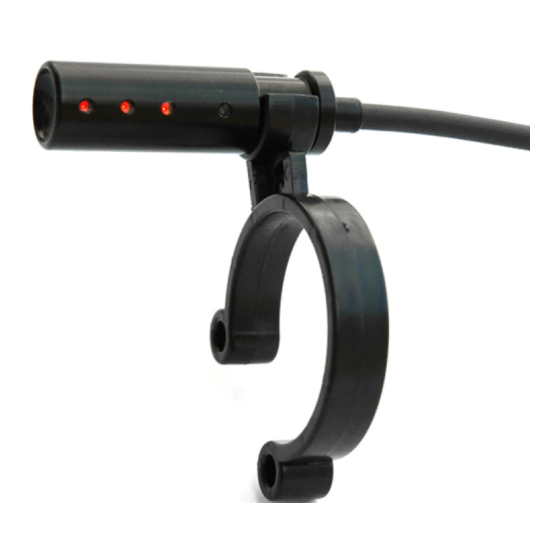
Display... - Page 13 Display The partial oxygen pressure is displayed via three dual color LEDs after successful calibration of the oxygen sensors. The LEDs are installed in an ultra compact device that can be mounted at every known CCR mouth piece without screws nor the necessity of glue.
-
Page 14: Blink Codes
Blink codes < 0.25bar: 8 x red Battery low: continuous blue 0.25-0.35bar: 7 x red 0.35-0.45bar: 6 x red Look at dive computer: blue LED blinking* 0.45-0.55bar: 5 x red 0.55-0.65bar: 4 x red 0.65-0.75bar: 3 x red Functionality of blue LED: 0.75-0.85bar: 2 x red If a diving computer is connected (S8 version only):... -
Page 15: Overview
Overview The ppO2 value is shown with a simple Scenarios: blink code. The code is repeated with up- dated values every five seconds. 0.4bar ppO2: red – red – red - red – red – red 0.7bar ppO2: red – red - red 1.0bar ppO2: yellow 1.3bar ppO2: green –... -
Page 16: Callibration
IMPORTANT: ble is not in mint conditon! Calibration prior to each dive / each power on is not obligatory (the hw HUD stores the latest calibration values) but The usage of at least two independent recommened to check for broken sen- monitoring devices for ppO2 is obliga- sors. - Page 17 Calibration IMPORTANT: The hw HUD has to be cali- NOTE: Sensors with less than 38mV out- brated with 100% oxygen. put @ 100% oxygen are rejected Both versions (S8 cable und stand-alone Channels without sensors will be deac- with optical out) are calibrated via the tivted until the next calibration.
-
Page 18: Installation
The setup has to be accomplished by person that is licenced to handle elec- tronic installations. The hw HUD electronic box is equipped with an 1m 8-wire cable for combined connection of HUD and sensors to achieve the most reliable wiring. Four... -
Page 19: Wiring Overview
The HUD is digitally controlled by the four wires of the electronic box mentioned in the overview. The high flex cable out of the HUD has four wires only. The colors of the wire are identical to those of the cable from the electronic box. -
Page 20: Wiring Hud
Wiring HUD Wire @ electronics box Wire @ HUB blue blue brown brown white white black black... -
Page 21: Wiring Sensors
Wiring sensors Wire @ electronics box Wire @ sensor grey GND/ground (–) yellow Sensor 1 positive terminal (+) Sensor 2 positive terminal (+) green Sensor 3 positive terminal (+) Sensors will be connected using a com- mon ground. The negative terminal of all sensors will be connected to the single grey cable of the electronic box. - Page 22 (soldering or crimping). Heat the rebreather head. shrink tubing (provided) has to be 3. Install the HUD cable in your re- used for each wire! breather head or sensor compart- 7. Install battery again. Check: the HUD...
-
Page 23: Installation Sequence
Installation sequence 8. Connect up to three ppO2 sensors to the remaining four cables ( most likely special connectors are neces- sary). Please keep in mind that all pins marked minus (–) are connect- ed to the single grey cable from the electonic box. -
Page 24: Battery Replacement
Battery replacement NOTE: hw HUD runs on 3.6V AA batteries. IMPORTANT: 1,5V AA batteries can not be used. For battery replacement use a coin to open the lid. The lid closes easily. Do not tilt the lid while closing the battery com- partment. - Page 25 Battery replacement A SAFT LS14500 AA 3,6Volt Battery is part Battery life depends on several factors of the hw HUD package and it should be i.e. Temperature, blink codes. As bench- replaced with the same battery by SAFT mark consider 200 hours with S8 version with AA dimensions and 3,6V.
-
Page 26: Maintenance
Maintenance... - Page 27 Maintenance The hw HUD is build as a low mainte- nance unit with safety features like per- fect sealed electronics. Rinse the complete setup of HUD and electronic box after dive with fresh wa- ter. Be careful to avoid any water drops to enter the system.
Need help?
Do you have a question about the HUD and is the answer not in the manual?
Questions and answers