Advertisement
Available languages
Available languages
Quick Links
®
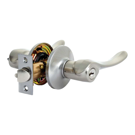
INSTRUCTIONS FOR INSTALLATION
OF LEVERS
For use on doors 1 3/8" to 1 3/4" (35 mm-45 mm) thick
model no.: 046-7231-0 to 046-7239-4
Toll-free Number: 1-800-268-6591
IMPORTANT
: Please read this manual carefully
before installing this deadbolt lock and save it for reference.
Adjustable latch for 2 3/8" (60 mm) and 2 3/4" (70 mm) backset
Backset is a distance from door edge to centr of hole on
door face.
Some locks are supplied with adjustable latch which can fit
2 3/8" (60 mm) or 2 3/4" (70 mm) backset.
Follow the steps shown below to change backset.
Before Proceeding :
The distance of backset which is from the edge of the door to the center of lock, either
2 3/8" (60 mm) or 2 3/4" (70 mm). Your latch was preset at the factory for 2 3/8" (60 mm)
backset.
If a 2 3/4" (70 mm) backset is required, follow the adjustment instructions in step 1a.
1a
1b
If 2 3/4" (70 mm) backset is required,
Be sure the stem hole of upper/lower
pull spindle cam all the way to the
cam is properly aligned.
right end of the adjusting hole.
1c
1d
Your latch is now set at 2 3/4" (70 mm)
To reset the latch to 2 3/8" (60 mm)
backset.
backset, push spindle cam to the
left end of the adjusting hole.
Latch Face Plate
Determine which latch mounting method will be
used and made necessary adjustments.
No adjustment required for square latch face plate.
To Change latch face :
1. Use a flat screwdriver to separate the face plate.
2. Snap selected face plate onto back plate.
Drive-in faceplate installation
Remove original faceplate.
Align the round faceplate with the latch bolt and
push it inside the latch bolt until you hear the catch click.
1. Mark the door with template
2. Drill holes
3. Install latch
a
e
b
c
d
Right
Wrong
Select 2 3/8" or 2 3/4" (60 mm or 70 mm) backset
as desired and mark centre of hole on door face.
a. Drill 2" (51 mm) hole through door face, from both
sides to avoid wood splitting.
b. Drill 1" (25.4 mm) hole for latch
(refer to step 3d for drive-in latch).
a. Insert latch in hole and keep it parallel to door face.
Mark outline of face plate and remove latch.
b. Chisel 5/32" (4 mm) deep inside traced outline or
until face plate is flush with door edge.
c. Insert latch and tighten screw.
d. For drive in latch, drill 1" (25.4 mm) hole and press
latch until it is flush with door edge.
Fold on dotted line and fit on door edge
45
40
35
1 3/4"
1 9/16"
1 3/8"
Mark 1" (25.4mm) hole at center of door edge.
4. Install strike
a. Close the door so the latchbolt is against the door frame.
a
b. Measure one half of door thickness from door stop
b
and vertically mark center line of strike.
Drill 1" (25.4 mm) hole, 1" (25.4 mm) deep at
intersection of horizontal and vertical line of strike.
Mark outline using strike plate and chisel
1/6" (1.6 mm) deep for strike.
c. Install strike and tighten screws.
c
5. Reversible levers
a. Make sure the levers are unlocked
a
(Entrance sets only).
Depress lever catch with hand tool to release
outside lever and pull lever off.
Take apart the spacer and cylinder from outside
lever.
b. Remove the spacers from inside lever with the
b
above procedures.
Reverse the levers from outside to inside/inside to
outside, putting the cylinder on the outside lever
(Entrance sets only) and replace the spacer.
Please do the same procedures for inside lever.
6. Install outside lever
Insert spindle through latch.
Press flush against door.
For 2 3/4" (70 mm) backset
For 2 3/8" (60 mm) backset
7/32" (5.5 mm)
x2 hole
2 1/4" (57 mm)
for metal door only.
7. Install inside lever
Install inside lever and tighten screws
untiI lock is tight.
ø
2 1/8" 54 mm
(
)
G-TL-01
Advertisement

Related Manuals for Garrison 046-7231-0


Summary of Contents for Garrison 046-7231-0
- Page 1 OF LEVERS For use on doors 1 3/8" to 1 3/4" (35 mm-45 mm) thick model no.: 046-7231-0 to 046-7239-4 2. Drill holes b. Measure one half of door thickness from door stop and vertically mark center line of strike.
- Page 2 Mesurez le point médian de l'épaisseur de la porte à partir de l'arrêt de porte et marquez verticalement le N° de modèle: 046-7231-0 to 046-7239-4 2. Percez les trous point central où sera percé le trou de la gâche.