
Related Manuals for WÄRTSILÄ SCENESCAN

Summary of Contents for WÄRTSILÄ SCENESCAN
- Page 1 SCENESCAN USER’S GUIDE Wärtsilä Guidance Marine Ltd, 5 Tiber Way, Meridian Business Park, Leicester, LE19 1QP, UK www.wartsila.com/guidance-marine T: +44 116 229 2600 E: sales.wgm@wartsila.com...
- Page 2 Copyright in the whole and every part of this document belongs to Wärtsilä Guidance Marine Limited (the “Owner”) and may not be used, sold, transferred, copied or reproduced in whole or in part in any manner or form or in or on any media to any person other than in accordance with the terms of the Owner’s Agreement or otherwise without the prior written consent of the Owner. “SceneScan” is a registered trademark of Wärtsilä...
- Page 3 Document History Document Number Changes Issue Date 94-0561-A First release of SceneScan User’s Guide 11/05/2018 94-0561-B Section added - How to report issues 17/12/2018 94-0561-C DNV-GL Certification logo added 08/04/2020 94-0561-D Wärtsilä DP Feed added and branding changed to Wärtsilä...
-
Page 4: Table Of Contents
Tracking Basics Cable Routing Diagrams Operating Blanking Zones Installing the Control PC Scanner Tilt Controls Tracking Installing SceneScan Client Software onto a Computer Tracking in Monopole Mode Upgrading the Sensor Software Positional Display Modes Configuring the SceneScan System Multi-Dashboard SceneScan Systems... -
Page 5: Introduction
1. Introduction Welcome System Overview SceneScan Sensor Part Names 94-0561-D... - Page 6 Welcome Introduction Welcome to the SceneScan User Guide. It explains how to: Note: Installation of a SceneScan system should be carried out by a suitably qualified and competent engineer. • Use the SceneScan system • Physically install the system •...
- Page 7 • The SceneScan Dashboard: The SceneScan Dashboard generates a visual representation of the scene detected by the SceneScan Sensor. It gives the DP Operator control of the system and the data stream being fed to the DP system. Both pieces of software run under Windows™ on a Type 4 Marine Processor or other (see page 57).
-
Page 8: Scenescan Sensor Part Names
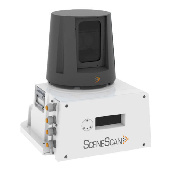
SceneScan Sensor Part Names Introduction The diagram below shows the key parts of the Sensor unit and the various names that are used throughout this guide: Optical Window Rotor Access Plate Power Sensor Information DP Feed 2 Display DP Feed 1... -
Page 9: Getting Started
2. Getting Started Start Up and Shut Down Targetless Tracking Screen Layout Tracking Information Quality Display Settings Vessel Orientation 94-0561-D... -
Page 10: Start Up And Shut Down
1. Ensure that the SceneScan Sensor is powered on. 2. Double-click on the SceneScan Dashboard icon. (Or run the SceneScan Dashboard from Start > All Programs > Guidance Marine Ltd > SceneScan > SceneScan Dashboard). 3. The Dashboard display screen will appear. - Page 11 Two types of blanking zone can be configured on a SceneScan system: • Fixed Blanking Zones – These can be exclusively configured using the SceneScan Service Interface. Fixed blanking zones are the Vessel Blanking Zone (Vessel Parameters) and the Static Blanking Zones.
-
Page 12: Targetless Tracking
We recommend that the user uses the blanking zones to constrain the scan area to that containing the monopole. By default SceneScan will select the centre of the tracked scene for the scene reference point, with a heading of 0°. - Page 13 Screen Layout Getting Started The SceneScan Dashboard screen is split into three distinct sections, these are: 1. Main Screen and Bird's Eye View (BEV) (see page 2. Side Bar (see page 3. Menu Pane (see page 94-0561-D...
-
Page 14: Screen Layout
Vessel Outline The Vessel Outline in the centre of the BEV represents the ship on which the SceneScan system is located, and the red dot denotes the SceneScan Sensor. The rotating fan-shaped symbol represents the laser beam emitted by the rotor as it turns. - Page 15 Scene Data Hotkeys Tab The Scene Data shows the scene detected by the SceneScan Sensor. The Hotkeys Tab is located on the right hand edge of the main pane. Note: The Scene Data can be constrained to a traditional circular BEV, Clicking on the tab will open the Hotkeys Menu.
- Page 16 Toggle Coordinate Type Signal Quality Coordinate Data DP Message Format Current Tilt Mode and Command Mode Start/Stop Tracking Button (It is always visible for SceneScan) Guidance Button After pressing the Guidance Button 94-0561-D...
- Page 17 Screen Layout (continued) Getting Started Hotkey Buttons Selecting the Hotkeys tab on the right-hand side of the main screen activates the Dashboard Hotkeys menu. The following keys - and the corresponding buttons on the Dashboard Hotkeys menu - act as shortcuts to application functions. Display Help Menu Toggle between the About System pane and the BEV display Rotates the Vessel Clockwise...
- Page 18 Getting Started Menu Pane The Menu Pane, located across the bottom of the SceneScan Dashboard Screen, is not always visible. It appears when one of the Tracking, Tilt or Advanced buttons near the foot of the Side Bar are pressed, which causes the Bird's Eye View (BEV) to contract towards the top of the screen.
-
Page 19: Tracking Information Quality
Tracking Information Quality Getting Started Once tracking is under way the Data Quality Bar indicates the level of confidence the system has in the quality of the scene data that is being acquired. The greater the size of the filled portion of the Data Quality Bar, the greater the level of confidence in the information. The colour of the Data Quality Bar and positional data also reflects the level of confidence: RED, YELLOW or GREEN, with GREEN meaning highest confidence. -
Page 20: Display Settings
Getting Started To provide ample visibility during daytime operation and to limit glare during night shifts, SceneScan Dashboard offers two display settings: Day Mode and Night Mode. In either mode the brightness can be further adjusted by the Screen Brightness control. - Page 21 Display Setting (continued) Getting Started The central BEV can be toggled between a traditional circular BEV, and The BEV can be further expanded to a full screen mode by pressing a full scene mode. Press F8 to toggle modes, or use the Toggle BEV F11, or using the Toggle Full Screen hotkey.
-
Page 22: Vessel Orientation
Vessel Orientation Getting Started SceneScan Dashboard supports four different layouts of the Bird’s Eye View so that Note: Changes made to the vessel orientation using the Dashboard are temporary and will revert back to the default setting when the Dashboard is restarted. The the operator can choose the one which best represents the vessel’s surroundings. -
Page 23: Tracking Basics
3. Tracking Basics Operating Blanking Zone Scanner Tilt Controls Tracking Tracking in Monopole Mode Positional Display Modes 94-0561-D... -
Page 24: Operating Blanking Zones
Sensor field of view. Note: Up to four additional static blanking zones can be configured from within the SceneScan Service Interface. These are used to mask segments of the scan rotation that are obscured by the vessel’s superstructure. -
Page 25: Scanner Tilt Controls
Manual - This mode is used to manually tilt the optics to point at the scene. For example, when station-keeping close to a platform where the superstructure is high up and the SceneScan beam must be tilted upwards. When starting tracking, the scanner will initially use the currently selected angle. No “sweep”... - Page 26 Tracking Tracking Basics To Start Tracking 1. Ensure that the Dashboard is In Command (see Command Mode). 2. Press the Start Tracking button. 3. Press Apply on the Apply/Cancel pop-up. Tilt Optimisation will start. The angle chosen will depend upon the current mode: •...
- Page 27 Scene Reference Point pending changes. This is the point within the scene that SceneScan will report its position Warning: Changing the Scene Reference Point will disable the DP Feed. This is relative to. By default SceneScan will select the centre of the tracked done because changing the reference point can dramatically alter the output from the DP Feed.
-
Page 28: Tracking
It is highly recommended that Auto tilt mode is used to start tracking when using scene data, but the Sensor will not have the DP Feed SceneScan. However, if a situation is encountered where tracking performance is enabled. The reason for this is to allow the operator... -
Page 29: Tracking In Monopole Mode
Tracking in Monopole Mode 1. Ensure that the Dashboard is In Command When in Monopole mode the SceneScan tracks the Range, Bearing and Radius of 2. Click on the Tilt button on the sidebar the monopole. We can also display the Bow and Starboard Axes. In this mode, the 3. -
Page 30: Positional Display Modes
Positional Display Modes Tracking Basics The relative positions of the SceneScan vessel and the Scene Range, Bearing and Heading Reference Point can be expressed either as Range and Bearing values, or as 'A' and 'B' positions on a rectangular coordinate frame. - Page 31 Positional Display Modes (continued) Tracking Basics A and B Axes (A Pos and B Pos) In this mode, the position of the Sensor vessel is expressed in metres from the scene along A and B axes which have their origin at the Scene Reference Point. The vessel's relative heading is measured clockwise from the A axis.
-
Page 32: Multi-Dashboard Scenescan Systems
4. Multi-Dashboard SceneScan Systems SceneScan Dashboard - Monitoring Mode SceneScan Dashboard - In Command Mode 94-0561-D... -
Page 33: Scenescan Dashboard - Monitoring Mode
2. Click on the Relinquish Command button. relating to the Dashboard itself will be active, but those relating to the SceneScan Sensor will be disabled. A Monitoring Dashboard displays the same scene as the In Command Dashboard. It cannot initiate or stop tracking operations, nor alter the power control, nor tilt settings. -
Page 34: Scenescan Dashboard - In Command Mode
Dashboard, whether it is Monitoring or In Command. When the Dashboard is in Command mode, it will When the In Command Dashboard is used to suspend the SceneScan automatically switch to Sensor, a message will appear on the screens of the Monitoring Monitoring mode when another Dashboards indicating that the system is suspended. -
Page 35: Support Information
5. Support Information Low Temperature Operation Work with Alarms Dynamic Positioning Feed Network Communications Settings Data Logging Serial Numbers & Software Versions 94-0561-D... - Page 36 It is recognised that industrial marine operations may subject these components to harsh environments, including low temperature. The SceneScan hardware complies with the requirements of IEC 60068-2-1 and is able to operate for prolonged periods at temperatures down to – 25°C provided that certain operating conditions are maintained.
-
Page 37: Working With Alarms
Working with Alarms Support Information During operation, the SceneScan system produces an audit trail of Fatal Alarms indicate a serious problem with the SceneScan system. event messages. These range in increasing order of severity from: Users should review the alarm details and follow any recommendations Information, Warning, and Error to Fatal. -
Page 38: Dynamic Positioning Feed
The Dynamic Positioning (DP) Feed is the data that SceneScan transmits to the vessel’s DP system. SceneScan supports several different data message formats and it is important that SceneScan and the DP system are both configured to use matching formats. However, this cannot be done from the Dashboard; in order to... -
Page 39: Network Communication Settings
Sensor IP address. Changing the Sensor's IP address (stored in the connect.ini file) is NOT possible from the dashboard but IS possible from the SceneScan Service Interface Network Config tab 'Sensor on-board network configuration' section (See page 61... -
Page 40: Data Logging
(see below). When logging is in progress, the following symbol is displayed in the bottom left- On a SceneScan system with multiple Dashboards, data logs are written by hand corner of the main pane. - Page 41 Data Logging (continued) Support Information Taking Screenshots The Grab Screenshot option records every detail of the current screen and stores it at the same location as the data logs. Up to ten screenshots are held and if a further screenshot is taken, the oldest of the existing ten is automatically deleted. To take a screen shot either: 1.
-
Page 42: Serial Numbers & Software Versions
Support Information Serial numbers and Software Version numbers are used to identify the hardware configuration and product revision of each SceneScan unit. They will be requested by Wärtsilä Guidance Marine in the event of an application service support call to the company. -
Page 43: Troubleshooting
6. Troubleshooting Problems and Possible Remedies SceneScan Fuse Information If your problem is not listed or you cannot resolve the issue, please contact the system installer or equipment provider who are trained to assist with installation and operational problems. If the problem cannot be resolved by the system installer or equipment provider, please contact Wärtsilä Guidance Marine Limited:... -
Page 44: Problems And Possible Remedies
DP output. Vessel Blanking Zone System operates correctly but in cold weather loses scene. SceneScan applies a blanking zone based on the dimensions of the vessel • Check for condensation or ice on the window of the Sensor. Clean if and position of the Sensor on the vessel. -
Page 45: Scenescan Fuse Information
SceneScan Fuse Information Troubleshooting The SceneScan system contains two replaceable fuses; one for the Live and the other for the Neutral. These are located on the connector board as shown below. Connector Board Fuse Please refer to SceneScan Sensor connections on page 51 on how to access the connector board. -
Page 46: Installing The Scenescan Hardware
7. Installing the SceneScan Hardware Where to Mount the Sensor Sensor Dimensions and Mounting Template 94-0561-D... - Page 47 Installing the SceneScan Hardware Sensor Mounting Locations The SceneScan system is designed for permanent or semi-permanent installation on-board a vessel. Often, a custom-fabricated plinth is used to provide the optimum height and location for mounting the SceneScan Sensor. On all types of vessel the Sensor should be mounted: •...
- Page 48 Sensor Dimensions and Mounting Template Installing the SceneScan Hardware Sensor Clearance Mounting Template The exact dimensions of the SceneScan unit’s footprint are shown Mount the baseplate horizontally. below. Additional information shown on the right could be beneficial when mounting the SceneScan unit. Please refer to Document No: 94-0062-4 CyScan Mounting Template to view the information in larger format.
-
Page 49: Installing The Cables
8. Installing the Cables Cable Specifications UPS Specifications SceneScan Sensor Connections SceneScan Client and DP Feed Connections Cable Routing Diagrams 94-0561-D... - Page 50 Installing the Cables The SceneScan system is usually supplied without the cables that are necessary to connect the Sensor to the DP system and the Client Software computer(s). Guidance recommends that flexible multicore cables are used in all applications. Cables should meet the requirements of IEC 60228 Class 2 or Class 5. Cables must be supplied and fitted by the installer to match the particular requirements for each vessel.
- Page 51 Nominal Current draw at 230V = 0.6A RMS • Voltage Range = 115 & 230V The SceneScan UPS should be able to run on back-up power for at • Frequency Range = 50-60Hz least the same duration as that specified for the DP System UPS.
-
Page 52: Scenescan Sensor Connections
1 TX- number: 190-0003-4) 1 TX+ into slot above connector-hole in plug. Whilst holding down lever, insert cable end into connector-hole. Release and remove the lever-tool. Base of SceneScan with the access cover removed to expose the connector board. 94-0561-D... -
Page 53: Scenescan Client And Dp Feed Connections
SceneScan Client and DP Feed Connections Installing the Cables Connect Ethernet Port 0 to the Marine Processor, Serial Port 1 to DP System 1 and Serial Port 0 to DP system 2. Configure the serial connections as shown below: Note: Either Serial 0 or Serial 1 can be used. - Page 54 Adaptor Marine Processor Box (Optional) Power Cable Monitor Power Cable Note: The Ethernet cable connecting the SceneScan Sensor to the Type 4 DP System UPS Marine Processor should not exceed Ethernet Emergency Breaker Box 90 metres in length. Ethernet Cable Please contact Wärtsilä...
-
Page 55: Cable Routing Diagrams
Cable Routing Diagrams (continued) Installing the Cables Alternative Processor and Monitor Options Any of the following configurations may be used (see page Hatteland Hatteland Touchscreen Monitor Panel PC Monitor Monitor Cable Monitor Cable Power Cable Type 4 Marine Processor Type 4 Marine Processor Ethernet Ethernet Cable... -
Page 56: Installing The Control Pc
9. Installing the Control PC Installing SceneScan Client Software onto a Computer Upgrading the Sensor Software Before setting up the SceneScan client computer(s), refer to the relevant installation sheet(s) for dimensions and connections information: For a Type 4 Marine Processor: •... -
Page 57: Installing Scenescan Client Software Onto A Computer
If you are upgrading to a The Dashboard newer version of the SceneScan client software you can simply install over the old version. may be installed onto multiple If you are downgrading to an older version of the software you must first uninstall the version you computers. -
Page 58: Upgrading The Sensor Software
Upgrading the Sensor Software Installing the Control PC To Upgrade the Sensor Software: 1. Ensure that the SceneScan Service Interface and Dashboard applications are not running. 2. Locate the file SceneScan.Installer.Remote.exe on the USB memory stick on which the SceneScan software was supplied. -
Page 59: Configuring The Scenescan System
10 Configuring the SceneScan System Using the Service Interface 10.1 10.2 Network Communication Settings 10.3 Vessel Parameters 10.4 Static Blanking Zones 10.5 Dynamic Positioning Feed Configuration 10.6 DP Feed Behaviour 10.7 System Parameters 10.8 DP Message Types 10.9 Service Schedule 10.10... -
Page 60: Using The Service Interface
Can be used to suspend/resume the sensor when In Command. Sensor Type - “SceneScan” if the SceneScan Service Interface is connected to a physical Sensor, “Emulator” if connected to the SceneScan Emulator application or “Blank” if not yet connected. Tracking State - “Not Tracking”, “Starting Tracking” or “Tracking”. -
Page 61: Network Communication Settings
10.2 Network Communication Settings Configuring the SceneScan System The Network Config tab of the SceneScan Service Interface is used To Modify the Sensor’s On-Board Network to view and amend the SceneScan Service Interface’s definition of its Configuration communications link with the Sensor, and it can be used to reconfigure the Sensor’s IP address. -
Page 62: Network Communication Settings
OK to reboot the Sensor. 1. Contact Wärtsilä Guidance Marine and obtain a new Sensor network configuration file (connect.ini). 2. Click on the Take Command button (if the SceneScan Service Interface is not already In Command). 3. Click on Browse. - Page 63 • Vessel Breadth: The width or beam of the vessel in metres. • Bow Offset: Distance from the centre of the SceneScan Sensor to the vessel’s bow, in metres. • Starboard Offset: Distance from the centre of the SceneScan Sensor to the vessel’s starboard side, in metres.
-
Page 64: Vessel Parameters
10.3 Vessel Parameters (continued) Configuring the SceneScan System Sensor Facing Forward Bearing Offset Connection panel facing aft, Sensor parallel with vessel centre-line. Enter the correct Bearing Offset value on the Vessel tab Bearing Offset = 180° • If the Sensor is facing directly Aft, enter a 0°... - Page 65 To Reset to Factory Defaults: 1. Click on the Resume button if the Sensor is suspended. 2. Ensure that no tracking is in progress. 3. Click on the Take Command button if the SceneScan Service Interface is not already In Command. Bow Offset 4.
-
Page 66: Static Blanking Zones
1. Click on the Resume button if the Sensor is suspended. 2. Ensure that no tracking is in progress. 3. Click on the Take Command button if the SceneScan Service Interface is not already In Command. 4. On the Blanking tab, click on the Edit button. -
Page 67: Dynamic Positioning Feed Configuration
1. Click on the Resume button if the Sensor is suspended. 2. Ensure that no tracking is in progress. 3. Click on the Take Command button if the SceneScan Service Interface is not already In Command. 4. On the DP Config tab, click on the Edit button. -
Page 68: Dp Feed Behaviour
10.6 DP Feed Behaviour Configuring the SceneScan System Formats: ASCII17, NMEA Raw, NMEA Primary, PGNMT, Formats: MDL Standard, Nautronix Std, ArtemisMk4, PGNKM MDL Multi-Scene, PGNRR Keep Feed Allow Zero Output Output Enabled Strings DP Feed State: Idle System State: Not Tracking No Output ... - Page 69 10.6 DP Feed Behaviour (continued) Configuring the SceneScan System 1. The DP Feed has 2 possible states: Idle and Tracking. It is in the Idle state if the system is not tracking or if the system is tracking but the DP Feed Output is disabled.
-
Page 70: System Parameters
25 for the Dashboard Tilt Menu. 3. Click on the Take Command button if the SceneScan Service Interface is not already In Command. Warning: Changing system parameters without supervision can result in 4. Click on the Parameters Tab. - Page 71 2. Ensure that the Sensor is not currently tracking. 1. Connect the SceneScan Service Interface to the sensor. 3. Click on the Take Command button if the SceneScan Service Interface is not 2. Click on the Parameters tab of the service interface.
-
Page 72: Dp Message Types
10.8 DP Message Types Configuring the SceneScan System NMEA Raw NMEA Primary A 42-character string: A 42 character string: $RLS,±AAA.AA,±BBB.BB,S1,XXX.XXX,S2,HHHH*CC<CR><LF> $RLS,±AAA.AA,±BBB.BB,S1,XXX.XXX,S2,HHHH*CC<CR><LF> Where: Where: • $RLS message header • $RLS message header • AAA.AA resolved raw position in A axis [metres] •... - Page 73 10.8 DP Message Types (continued) Configuring the SceneScan System ASCII17 † Nautronix Standard A 17 character string delimited only by <CR> and <LF> with bearing measured bow A 14 character string delimited only by <CR> and <LF> with bearing measured bow clockwise.
- Page 74 The ‘age’ is the accumulated time in milliseconds Proprietary header 6 chars from the moment the measurement was made until Type field for SceneScan [S] 1 char the moment the message string is constructed, prior HH_MM_SS.SSS Real-time clock time at message transmission to DP 12 chars to being transmitted to the DP system.
- Page 75 The ‘age’ is the accumulated time in milliseconds Proprietary header 6 chars from the moment the measurement was made until Type field for SceneScan [S] 1 char the moment the message string is constructed, prior YYYY MM DD Real-time clock date at message transmission to DP [1-9] 10 chars to being transmitted to the DP system.
- Page 76 10.8 DP Message Types (continued) Configuring the SceneScan System Kongsberg (Custom) The Kongsberg Custom DP string adopts NMEA0183 conventions and has a length of 40 characters. Two messages are emitted per rotor revolution, one for the Scene Reference Point and one for a secondary, virtual reference point (that is at a fixed offset from the Scene Reference Point).
- Page 77 10.8 DP Message Types (continued) Configuring the SceneScan System NMEA Wärtsilä (Custom) The NMEA Wartsila custom DP string adopts NMEA0183 conventions and has a length of 109 characters. $RLSX,±AAA.AA,±BBB.BB,S1,XXX.XXX,S2,GGHH.MMMMMMM,N,PPPQQ.RRRRRRR,T,S3,D.DD,E.EE,F.FF,±.JJJ,±.KKK,±.LLL,HHHH*CC<CR><LF> Where: • $RLSX Message Header 5 chars • ±AAAA.AA Resolved raw position in A axis [metres] 7 chars • ±BBBB.BB...
- Page 78 10.8 DP Message Types (continued) Configuring the SceneScan System NMEA Wärtsilä (Custom) This message supplies the position and heading of the reflector constellation relative to sensor. This can also be interpreted as the position and heading of the sensor relative to the reflector constellation if we adopt the appropriate frame of reference and sign convention.
-
Page 79: Service Schedule
10.9 Service Schedule Configuring the SceneScan System Sensor Maintenance Requirements and Recommended Storage Conditions Frequency Procedure Notes • Weekly Clean rotor window • 3 - Yearly Replace silica gel There are four silica gel bags (part#: 98-0001-4) within the SceneScan: •... -
Page 80: Scenescan Installation Checklist
10.10 SceneScan Installation Checklist Configuring the SceneScan System Vessel name: ............SceneScan unit s/n: ................. Computer s/n: ............. Check Requirement Checked Notes/record Check Requirement Checked Notes/record setting setting (Initial) (Initial) Mechanical Sensor Details / Vessel Calibration Sensor Line of sight to expected Scene... - Page 81 Scene Reference Point 12, 14, 27, 73, 74, 75, 76 Kongsberg Custom DP String 76 SceneScan Dashboard 7, 10 Base Plate 8 SceneScan Service Interface (SSI) 60 Bearing Offset 47, 63, 64 Screen Layout 13 Blanking Zones 12, 24, 66...
- Page 82 94-0561-D...
Need help?
Do you have a question about the SCENESCAN and is the answer not in the manual?
Questions and answers