
Summary of Contents for Core Health & Fitness StarTrac Stairmaster 15” Capacitive Touch OpenHub Embedded Console
- Page 1 CORE HEALTH & FITNESS 15”-19” Capacitive Touch OpenHub Embedded Console OWNER’S MANUAL...
-
Page 2: Table Of Contents
TABLE OF CONTENTS IMPORTANT SAFETY INSTRUCTIONS ........................2 IMPORTANT LABEL LOCATIONS ..............4 PRODUCT SPECIFICATIONS ........................5 INITIAL SETUP ..............6 OPERATION - OPENHUB TOUCHSCREEN CONSOLES ........................7 SCREEN VIEWS ..............10 WORKOUT SELECTION KEYS AND PROGRAM DEFINITIONS ....12 PROGRAM UPLOAD ..............13 MENU MAP ........................15 8G/10G... -
Page 3: Important Safety Instructions
IMPORTANT SAFETY INSTRUCTIONS WARNING! Before using this product, it is essential to read the ENTIRE Owner’s Manual and ALL installation instructions. The Owner’s Manual describes equipment assembly and instructs members on how to use correctly and safely. Read all warnings posted on the machine. Health related injuries may result from incorrect or excessive use of exercise equipment. - Page 4 Do not exceed the maximum allowable weight limit of the base unit. Refer to the Owner’s Manual for the machine base connected to the unit. Use only replacement components supplied by Core Heath & Fitness. Substitutes are forbidden and will void all warranties. This machine is not intended to be used by persons with reduced physical, sensory, or mental capabilities or lack of experience and...
-
Page 5: Important Label Locations
IMPORTANT LABEL LOCATIONS This page shows the location of the warning labels and communication stickers placed on the equipment as part of the manufacturing process. It is critical that owners maintain the integrity and placement of these stickers. If you find any stickers missing or damaged the replacement numbers are shown on the support site. - Page 6 PRODUCT SPECIFICATIONS OpenHub Embedded Console Fig. 2 SKU: 700-0463-XX Desc: 19” Tread-NTC 700-0466-XX 19” Tread-PAL-DMB Overall Weight Width Length Height 23 lbs (10.4 kg) 20.7 in (53 cm) 28.9 in (73 cm) 9.8 in (25 cm) SKU: 700-0471-XX Desc: 15” ST-BCS-ATSC 700-0472-XX 15”...
-
Page 7: Initial Setup
INITIAL SETUP After powering the unit for the first time, the computer will boot up and the Select Device screen will appear in the display. If for any reason the screen does not appear, on the top of the touchscreen, tap the upper left corner, then upper right, then upper left again. - Page 8 OPERATION - OPENHUB TOUCHSCREEN CONSOLES Fig. 5 Treadmill Hotbar CONSOLE & HOTBAR (WHERE APPLICABLE) FUNCTIONS Enables manual operation using a default weight, SPEED and a default time limit. QUICK START Key NOTE: Default time and weight are adjustable through Maintenance Mode. Press the STOP button to enter pause mode.
- Page 9 Incline Adjustment Allows user to increase/decrease incline (Treadmill/Treadclimber Only) Level Adjustment Allows user to increase/decrease program level (8G and 10G Only) RunTV ST20 H.I.I.T. Main Menu Workout controls, varies by unit. See the Menu Map for complete details. Build A Workout Existing Workouts...
- Page 10 BLUETOOTH DEVICE PAIRING Pushing the button opens the bluetooth menu. After selecting the device type, the console will show all available local devices. The display will show the unique console code. Once a device is paired with the console, the light will stop flashing and remain on to indicate the connection. Visit openhubconnect.com for a list of compatible apps and demonstration video.
-
Page 11: Screen Views
SCREEN VIEWS 3.65mi 37:45 20:00 KCAL Total Distance Total Time Pace (Min/Mi) 0.15 15.0 15.0 MILES Fig. 7 Screen Elements During most workouts, users can select from multiple screen view options by tapping the icons at the bottom of screen. Screens vary by unit, all screens are shown in the Service Manual. •... - Page 12 Other controls vary by unit: Fan Button Cycles the fan between three settings: High, Low and Off Bluetooth Button is grayed out if no device is connected to the console. Adjustment Allows user to increase/decrease speed, level or incline depending on unit. Buttons This button has the same function as pressing stop button on hot bar, puts Exit/Back...
-
Page 13: Workout Selection Keys And Program Definitions
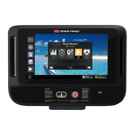
WORKOUT SELECTION KEYS AND PROGRAM DEFINITIONS On the main screen are several choices: Quick Start Program will request user information to create more accurate calorie burn and heart rate zone calculations, then begin a fixed time (default length can be adjusted in maintenance mode) manual workout Existing Workouts 5K Time Trial Manual... -
Page 14: Program Upload
PROGRAM UPLOAD Prior to starting a workout, a BlueTooth connected device can be used to upload a program to display on the console from a compatible app. The upload may contain user info such as age and weight. RunTV 1. In an App interface, select the option to Upload Program ST20 to Display and then select... - Page 15 3. Once the program has loaded, press the green start button to RunTV progress to the setup screen. ST20 H.I.I.T. NOTE: Console will return to home screen after 30 seconds Build A or if cancel is pressed. Workout Existing 4. If program fails to load, an Workouts error screen is displayed for 5 seconds before retuning to...
-
Page 16: 8G/10G
MENU MAP 8G/10G RunTV SM20 H.I.I.T. Landmark Challenge Build A Workout Build A Workout Custom Time Floor Calorie Training Interval Goal Goal Goal Tools Quick Start Training Tools Constant HR Dynamic HR CPAT Dutch FF Control Control HR Check Fig. 15 8G or 10G Menu Map Page 15... -
Page 17: Treadmill
TREADMILL RunTV ST20 H.I.I.T. Build A Workout Build A Workout Custom Time Distance Calorie Improve Interval Goal Goal Goal Cardio HR Training Constant HR Dynamic HR Control Control Existing Workouts Existing Workouts Manual Random Hill Alpine Pass 5K time trial Evaluate Fitness Quick Start... -
Page 18: Freeclimber
FREECLIMBER RunTV SM20 H.I.I.T. Landmark Challenge Build A Workout Build A Workout Custom Time Floor Calorie Improve Interval Goal Goal Goal Cardio Quick Start HR Training Constant HR Dynamic HR Control Control Fig. 17 Freeclimber Menu Map Page 17... -
Page 19: Bike/Crosstrainer
BIKE/CROSSTRAINER RunTV ST20 H.I.I.T. Build A Workout Build A Workout Custom Time Distance Calorie Improve Interval Goal Goal Goal Cardio HR Training Constant HR Dynamic HR Control Control Existing Workouts Existing Workouts Manual Random Hill Alpine Pass Autopilot Training Tools Quick Start Training Tools... - Page 20 MAINTENANCE MODE Maintenance Mode allows access to service and diagnostic information, as well as provides the ability to adjust certain program default parameters. To enter Maintenance Mode: On the top of the touchscreen, tap the upper left corner, then upper right, then upper left again. Password Screen will display.
- Page 21 Fig. 22 Maintenance Mode TM (default values shown) MAINTENANCE MODE While in Maintenance Mode, the following information can be accessed and/or modified: • SW versions - The latest software version loaded in the system. • Serial Number - The last five digits of the display serial number. •...
- Page 22 Fig. 23 Manager Mode (default values shown) MANAGER MODE While in Manager Mode, the following information can be access and/or modified: • SW versions - The latest software version loaded in the system. • Serial Number - The last five digits of the display serial number. •...
- Page 23 Fig. 24 Network Mode (Ethernet Connected) NETWORK MODE Internet connection information and network settings are shown and changed in this screen. An internet speed of 4mbps for up to 4 machines, then an extra mbps for every additional 4 machines is recommended. Connecting to WIFI Tap Enable RF if not active.
- Page 24 Tap Scan Wireless Select the correct network then tap Add Network. Fig. 26 Network: Select Network Enter the key in the PSK field then tap Connect Fig. 27 Network: Enter Key Once connected, current connection information appears in the upper right and the active connection is green.
- Page 25 Fig. 29 Diagnostic Mode DIAGNOSTIC MODE Allows the test of all hard keys, and the telemetry and contact heart rate. Page 24...
- Page 26 Fig. 30 Usage Statistics USAGE STATISTICS Displays the total number of times a program has been used (programs will differ by equipment type. Page 25...
- Page 27 Fig. 31 Last Error List LAST ERROR LIST MODE The top row displays the last 5 recorded errors with corresponding data below. Page 26...
- Page 28 Fig. 32 Calibration & Setup Main Screen CALIBRATION & SETUP The Calibration and Setup screen allows you to calibrate your equipment, update software, customize the user interface and setup the TV. Note: the Calibration and Setup screen is different for each product type. Speed Calibration Procedure Select Speed Calibration on the Calibration and Setup...
- Page 29 Incline Calibration Procedure Select Incline Calibration on the Calibration and Setup screen. Press START to begin the calibration. After the Speed Calibration is completed, press EXIT; The Calibration And Setup screen appears. Press to exit and go back to the Home Screen. The Incline Calibration has been completed.
- Page 30 App Selection Select App Selection on the Calibration and Setup screen. Press an app icon to select or deselect an app. If app is deselected, it will not be available to the user. Once changes are made, press to save and exit or press to cancel and exit.
- Page 31 Import Images Using the integrated USB port, it is possible to upload custom graphics and images. 1. Upload up to 7 custom images to be used as the background for the home and setup screens 2. Upload a custom logo for the top center of the home screen Fig.
- Page 32 File Location It is important to place the files on the USB drive in a specific location. If the files are not placed in /images/ as shown, the image files will not upload to the console. The total size of all images combined cannot exceed 20 MB.
- Page 33 Fig. 42 - Tuner Main Screen TUNER Select entertainment input. Selecting Tuner will open up the channel dialog: Channel Scan Procedure Select Channel Scan on the Tuner Configuration screen. Fig. 43 Select Tuner Select the signal type from the Scan Mode option (Both, Analog or Digital).
- Page 34 Channel Editing Select a channel on the Tuner Configuration screen. Tap ‘edit selected’. In the dialog box that opens, use the ‘visible’ box to add or remove access to the channel from the console, or to rename the channel. Fig. 45 Channel Edit Dialog Channels can be moved from one Capacitive Touch OpenHub console to another with an empty USB flash drive, preventing the need to scan on every unit during an install.
- Page 35 Fig. 46 Set Top Box Main Screen Set Top Box Select entertainment input. Selecting STB will open up the STB screen. Preset STB’s are selected from the dropdown and by default include the following options (may change without notice): • AMINO •...
-
Page 36: Error Codes
ERROR CODES Error Codes for Treadmill, Bike, Crosstrainer, and Versastrider machine configurations Error Code Name Meaning/Definition Model Mismatch Invalid equipment configuration is currently selected. LCB Comms Communications with the Lower Control board has been lost Lost Stuck key The key switch circuit has been closed for an excessive period of time. Over Speed Speed has exceeded the maximum specified speed of the machine by 3.0 miles per hour. - Page 37 Error Codes for Gauntlet and Freeclimber machine configurations Error Code Name Meaning/Definition Invalid Model Invalid equipment configuration is currently selected. EEPROM failure A failure of the system’s non-volatile memory has been detected. Stuck key The key switch circuit has been closed for an excessive period of time. LCB Com Error Communications with the Lower Control board has been lost App CRC Failed...
-
Page 38: Logged Data
LOGGED DATA When an error occurs, additional system data that represents the state of the system at the instance the error occurs is recorded as an entry into a list of error log entries visible from the maintenance mode. The total number of error log entries is 10. -
Page 39: Treadmill Frame
INSTALLATION TREADMILL FRAME 1. Use a #2 phillips screwdriver to secure the console back shroud to the mast using eight (8) pieces each of the #8-18 x 3/4” pan head screw (#110-3402) and M4 washer #120-3307 . Note: On 8-TR or 8-TRx with a Gen 1 Hotbar only, install grommet 020-7884-XX as shown in Fig. - Page 40 GROUND TO MAST GROUND TO MAST Fig. 50 19” Example Console *E and F are pre-wired to the back console shroud in the location shown in Fig. 51: Fig. 51 Page 39...
- Page 41 3. Use a #2 phillips screwdriver to secure the console front to the back shroud using eight (8) pieces of the #8-18 x 3/4” pan head screw. Note: For 8-TR with a 19” screen only, follow the directions for 8-TR Only on page Fig.
- Page 42 8-TR Only 1. Use a #2 phillips screwdriver to remove the screw securing the audio PCB to the hotbar audio mount. NOTE: Keep this screw as it is reused in Step 5. Fig. 55 2. Disconnect the cables attached to the HDMI panel.
- Page 43 5. Secure the audio PCB into the HDMI panel using the screw removed in Step 1. 6. Reinstall the HDMI panel using the screws removed in Step 3. 7. Reconnect the cables to the HDMI panel. Fig. 58 8. Connect the audio PCB to the console using the male-to-male 3.5mm audio cable.
-
Page 44: Bike/Ct/Vs Frame
BIKE/CT/VS FRAME 1. Use a #2 phillips screwdriver to secure the console back shroud to the mast using eight (8) pieces each of the #8-18 x 3/4” pan head screw and M4 washer. Fig. 61 8-VS ONLY TO FRAME FOR 3RD MAST PARTY ACCESSORY... - Page 45 GROUND TO MAST GROUND TO MAST Fig. 63 15” Example Console *E and F are pre-wired to the back console shroud in the location shown in Fig. 64: Fig. 64 Page 44...
- Page 46 3. Use a #2 phillips screwdriver to secure the console front to the back shroud using seven (7) pieces of the #8-18 x 3/4” pan head screw. Fig. 65 4. After powering the unit for the first time, the computer will boot up and the Select Device screen will appear in the display.
-
Page 47: G/Fc Frame
G/FC FRAME 1. Use a #2 phillips screwdriver to secure the console back shroud to the mast using eight (8) pieces each of the #8-18 x 3/4” pan head screw and M4 washer. Fig. 67 ONLY FOR 3RD PARTY ACCESSORY Fig. - Page 48 GROUND TO MAST GROUND TO MAST Fig. 69 15” Example Console *E and F are pre-wired to the back console shroud in the location shown in Fig. 70: Fig. 70 Page 47...
- Page 49 3. Install Audio Inserts (8-G Only) Use a #2 phillips screwdriver to remove the screw securing the headphone PCB to the USB-HDMI panel, then remove the head- phone PCB. (See Fig. 71) Fig. 71 Install the headphone PCB into the hotbar insert using the screw removed in the previ- ous step.
- Page 50 Fig. 74 5. After powering the unit for the first time, the computer will boot up and the Select Device screen will appear in the display. 6. Perform the “INITIAL SETUP” on page 6 to complete installation. Page 49...
- Page 51 8-G (9-5250) Only 1. Use a #2 phillips screwdriver to remove the PCB from then Gen 2 audio insert then install it into the Gen 1 audio insert. Fig. 75 2. Use a #2 phillips screwdriver to remove the screw securing the hotbar cap into the hotbar, then remove the cap.
- Page 52 8-G (9-5270) Only 1. Use a #2 phillips screwdriver to remove the screw securing the hotbar cap into the hotbar, then remove the cap. Fig. 78 2. Install the Gen 2 audio insert, then secure with the screw removed above. Fig.
- Page 53 SUPPORT & SERVICE For Technical Support, Service, Parts Orders or any Customer Service needs, please contact us direct by phone, email, or through our 24 hour support site: GLOBAL SUPPORT CENTER 4400 NE 77th Avenue, Suite 300 Vancouver, WA 98662 Tel: (360) 326-4090 •...
- Page 54 © 2020 CORE HEALTH & FITNESS LLC PART NUMBER 620-8642, REV D All rights reserved. Star Trac, the Star Trac logo and StairMaster are registered trademarks of Core Health & Fitness, LLC. Schwinn and Nautilus are registered trademarks of Nautilus Inc. used under license to Core Health & Fitness LLC. Throwdown is a registered trademark of Throwdown Industries, LLC.
Need help?
Do you have a question about the StarTrac Stairmaster 15” Capacitive Touch OpenHub Embedded Console and is the answer not in the manual?
Questions and answers