Advertisement
Available languages
Available languages
Quick Links
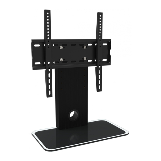
FS306
alle Farbvarianten
TV STAND
100x100
400x100
400x200
200x100
400x300
200x200
400x400
300x200
300x300
MONTAGEANLEITUNG
ACHTUNG: NIEMALS DAS MAXIMAL
ZULÄSSIGE BELASTUNGSGEWICHT
ÜBERSCHREITEN. MISSACHTUNG
KANN ZU SACHSCHÄDEN ODER
SCHWEREN VERLETZUNGEN FÜHREN!
40kg
(88lbs)
MAX
Deutsch
v.16.12
English
Advertisement

Summary of Contents for VESA FS306
- Page 1 TV STAND MONTAGEANLEITUNG v.16.12 ACHTUNG: NIEMALS DAS MAXIMAL ZULÄSSIGE BELASTUNGSGEWICHT ÜBERSCHREITEN. MISSACHTUNG KANN ZU SACHSCHÄDEN ODER SCHWEREN VERLETZUNGEN FÜHREN! FS306 40kg 100x100 400x100 400x200 200x100 (88lbs) 400x300 200x200 400x400 alle Farbvarianten 300x200 300x300 Deutsch English...
- Page 2 ACHTUNG: Lesen Sie die gesamte Bedienungsanleitung durch, bevor Sie mit der Montage beginnen. WARNUNG • Bitte beachten: Bilder in dieser Montageanleitung stellen nur technische Darstellung des Produktes dar. Tatsächliches Produktdesign kann minimal abweichen. • Beginnen Sie nicht mit der Montage, bis Sie alle Anweisungen und Warnungen, welche in dieser Montageanleitung vorhanden sind, durchgelesen und verstanden haben.
- Page 3 Lieferumfang WICHTIG: Stellen Sie vor der Montage sicher, dass alle Teile welche hier aufgeführt sind, bei der Lieferung dabei sind. Sollten Teile fehlen oder defekt sein, kontaktieren Sie Ihren Händler. G1 (x2) A1 (x2) A2 (x2) B4 (x2) A3 (x4) A4 (x8) A5 (x4) A6 (x4)
- Page 4 Den Lochabstand vor der Montage nachmessen Bitte überprüfen Sie VOR der Montage den Lochabstand zwischen den VESA-Befestigungs-lö- chern an Ihrem Bildschirm! VESA-Befestigungslöcher Vertikal / Senkrecht Horizontal / Waagerecht Bildschirm Rückseite Diese Wandhalterung unterstützt folgende Lochabstände: min. 30mm - max. 425mm Horizontal / Waagerecht min.
- Page 5 Schritt 2 G1 (x2) Deutsch English...
- Page 6 Schritt 3 A2 (x2) A1 (x2) Deutsch English...
- Page 7 Schritt 4 A4 (x4) A3 (x4) A5 (x4) A4 (x4) A6 (x4) Deutsch English...
- Page 8 Schritt 5 Schritt 6 ODER ODER ODER Deutsch English...
- Page 9 Schritt 7 Bildschirm Deutsch English...
- Page 10 Schritt 8 B4 (x2) Wartung • Prüfen Sie in regelmäßigen Abständen (mindestens alle drei Monate), ob alle Schrauben an dem Produkt fest angezogen sind. • Bei Fragen kontaktieren Sie Ihren Händler. Fertig Deutsch English...
- Page 11 TV STANDS INSTALLATION MANUAL v.16.12 CAUTION: DO NOT EXCEED RATED LISTED WEIGHT. SERIOUS INJURY OR PROPERTY DAMAGE MAY OCCUR! 40kg FS306 400x100 100x100 200x100 400x200 (88lbs) 400x300 200x200 400x400 300x200 all color variations 300x300 English Deutsch...
- Page 12 NOTE: Read the entire instruction manual before you start installation and assembly. WARNING • Please note: Images in these assembly instructions are only technical presentation of the product. Actual product design may vary minimally. • Do not begin the installation until you have read and understood all the instructions and warnings contained in this installation sheet.
- Page 13 Component Checklist IMPORTANT: Ensure that you have received all parts according to the component checklist prior to installation. If any parts are missing or faulty, telephone your local distributor for a replacement. G1 (x2) A1 (x2) A2 (x2) B4 (x2) A3 (x4) A4 (x8) A5 (x4)
- Page 14 Measure distance between mounting holes Please check BEFORE installation distance between VESA mounting holes on your display! VESA-Mounting holes Vertical / Perpendicularly Horizintally Display back This wall mount supports the following distance between holes: Horizontally min. 30mm - max. 425mm Vertical / Perpendicularly min.
- Page 15 Step 2 G1 (x2) English Deutsch...
- Page 16 Step 3 A2 (x2) A1 (x2) English Deutsch...
- Page 17 Step 4 A4 (x4) A3 (x4) A5 (x4) A4 (x4) A6 (x4) English Deutsch...
- Page 18 Step 5 Step 6 English Deutsch...
- Page 19 Step 7 Display English Deutsch...
- Page 20 Step 8 B4 (x2) Wartung • Prüfen Sie in regelmäßigen Abständen (mindestens alle drei Monate), ob alle Schrauben an dem Produkt fest Maintenance angezogen sind. • Check that the bracket is secure and safe to use at regular intervals(at least every three months). •...
Need help?
Do you have a question about the FS306 and is the answer not in the manual?
Questions and answers