Table of Contents
Advertisement
Quick Links
Advertisement
Table of Contents

Subscribe to Our Youtube Channel
Related Manuals for QCT Rackgo X


Summary of Contents for QCT Rackgo X
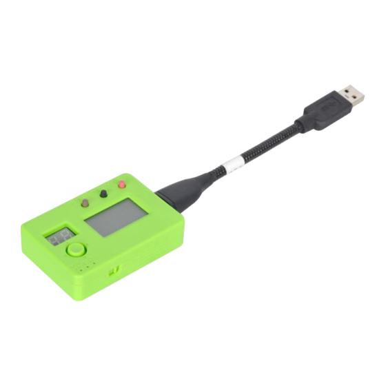
- Page 1 QCT Rackgo X OCP Debug Card with LCD 2018/10/15...
-
Page 2: Table Of Contents
Agenda • Overview • High Level Features • Mechanical View & Interconnection • Why Needs This Product • Key Part Placement • UART Connection with Host • LED Panel Content & Display • Design Files Contribution • OCP Tenets/Principles • Summary... -
Page 3: Overview
Overview • Introduction - ‘’QCT Rackgo X OCP Debug Card with LCD’’ is to intend to ease the debug effort and time consumed. It already has successfully approved the obvious improvement of the service efficiency with various compatible systems, for instance, ‘’Tioga Pass’’... -
Page 4: High Level Features
High Level Features Product Description Prodcut Description Rackgo X OCP Debug Card with LCD DImension Dimension 70.55 mm(L)x48mm(W)x17.1mm(H) Electrical Interface 1. USB 3.0 Connector with remapped proprietary singal pin, the USB3.0 connector will downgrade to support USB2.0 speed only --USB2.0... -
Page 5: Mechanical View & Interconnection
Mechanical View & Interconnection Baseboard IO side • ‘’Debug card with LCD’’ will be plugged (Tioga Pass) to remapped USB3.0 connector of the baseboard by cable connection Debug card with LCD... -
Page 6: Why Needs This Product
Why Needs This Product ➢ What is the real situation we are facing now - For data center user: No user friendly debug utility when troubleshooting in their working environment - For server baseboard designer: Hard to find enough IO space for the debug-purpose I/O ports •... -
Page 7: Key Part Placement
Key Part Placement Source:Fcebook_OCP_Debug_Card_with_LCD_Spec_v1p0... - Page 8 Block Diagram Source:Fcebook_OCP_Debug_Card_with_LCD_Spec_v1p0...
-
Page 9: Uart Connection With Host
UART Connection with Host ➢ UART Connection between Server Board to host side... -
Page 10: Led Panel Content & Display
LED Panel Content & Display • The display provide the information below: – POST Code Frame – System Info Frame – Critical SEL Frame – Critical Sensor Frame – GPIO Status Frame • If any sensor is out of the threshold, the whole screen should blink and invert the color for the sensors which out of the threshold... - Page 11 Compatible Components List & User Guide • ‘’QCT Rackgo X OCP Debug Card with LCD’’ could be operated with – Tioga Pass sled – Yosemite V2 sled QCT Rackgo X OCP Rackgo X Tioga Pass Sled Debug Card with LCD...
- Page 12 Possibility Of Been Compatible With Previous Generation Platform [Quanta] Technically, it is doable to make the previous revision system with old debug interface to communicate with the new revision debug card by adding one PCA9555 in the interposer card. But it is still a limited communication, it cannot completely demonstrate the full function of the new debug card.
-
Page 13: Design Files Contribution
Design Files Contribution- 01_Electricals ➢ 01_Full System Board Layout ➢02_Full System Schematic CAD... - Page 14 Design Files Contribution- 01_Electricals ➢ 03_Full System Component BOM ➢04_Manufacturing Files...
- Page 15 Design Files Contribution- 02_Mechanicals ➢ Mechanical files...
- Page 16 Design Files Contribution- 03_Software ➢ Software files...
-
Page 17: Ocp Tenets/Principles
OCP Tenets/Principles • Efficiency - To Integrate debug utility & debug message into one small box without separated utilities and extra effort - Reserve more front end IO space for more critical IO expansion • Scalability - Comply with common debug protocol, like UART, USB •... - Page 18 Summary • We have already released our patch code of the debug card to GitHub as below – https://github.com/Quanta-Computer/Debug-Card...
- Page 19 Thanks!!!
Need help?
Do you have a question about the Rackgo X and is the answer not in the manual?
Questions and answers