Table of Contents

Subscribe to Our Youtube Channel
Summary of Contents for DIGITAL-LOGIC MICROSPACE MSMVA104+
- Page 1 TECHNICAL USER'S MANUAL FOR: PC/104 and peripheral board MSMVA104+ Nordstrasse 11/F CH- 4542 Luterbach Tel.: ++41 (0)32 681 58 00 Fax: ++41 (0)32 681 58 01 Email: support@digitallogic.com Homepage: http://www.digitallogic.com...
- Page 2 DIGITAL-LOGIC AG MSMVA104+ Manual V1.0C COPYRIGHT © © © © 1992- 2006 BY DIGITAL-LOGIC AG No part of this document may be reproduced, transmitted, transcribed, stored in a retrieval system, in any form or by any means, electronic, mechanical, optical, manual, or otherwise, without the prior written permission of DIGITAL-LOGIC AG.
-
Page 3: Table Of Contents
DIGITAL-LOGIC AG MSMVA104+ Manual V1.0C Table of Contents PREFACE..........................4 ........................4 OW TO USE THIS ANUAL ............................4 RADEMARKS ............................4 ISCLAIMER ......................4 HO SHOULD USE THIS RODUCT ........................5 ECYCLING NFORMATION ..........................5 ECHNICAL UPPORT ..........................5 IMITED ARRANTY OVERVIEW ......................... 6 ........................6 RDERING NFORMATION ........................6... -
Page 4: Preface
The specifications given in this manual were correct at the time of printing; advances mean that some may have changed in the meantime. If errors are found, please notify DIGITAL-LOGIC AG at the address shown on the title page of this document, and we will correct them as soon as possible. -
Page 5: Recycling Information
DIGITAL-LOGIC AG), wrong connection, wrong information or as a result of service or modification by anyone other than DIGITAL-LOGIC AG. Neither, if the user has not enough knowledge of these technologies or has not consulted the product manual or the technical support of DIGITAL-LOGIC AG and therefore the product has been damaged. -
Page 6: Overview
DIGITAL-LOGIC AG MSMVA104+ Manual V1.0C VERVIEW Ordering Information Ordering Information: MSMVA104+ VGA controller with CRT, TV-OUT (or second CRT), DVI and LVDS General Information The product MSMVA104+ can be described as following: PC/104+ PCI Bus 120 pin with selectable PCI slot... - Page 7 3D apps single display Average: 1.7 W Max 3.9 W 3D Game Average: 3 W Max: 4.5 W These are average and max dissipitation from the ASIC, for the whole card, please ask Digital-Logic. Ordering Information: MSMVA104+ Art Nr: 801625...
-
Page 8: Multimedia, Power And Display Features
DIGITAL-LOGIC AG MSMVA104+ Manual V1.0C Multimedia, power and display features The MSMVA104+ with its flexible display support, 2D and 3D acceleration and reduced power consumption includes following features: Multiple display support with hydravision software (multiple desktop on one or more displays) like... -
Page 9: Software
Win98, Win2000, WIN NT4.0, WinXP Hydravision CD:\bios\ati_vga_bios VGA Bios Atiflash.exe VGA Bios download tool Core Bios CD:\bios\ PIII BX_core_bios BX core Bios for use with Digital-Logic AG MSM-P3-SEN core Bios, for other MSMVA104+ product, please ask Digital-Logic AG MSMVA104+ Manual CD:\manual\ This document... -
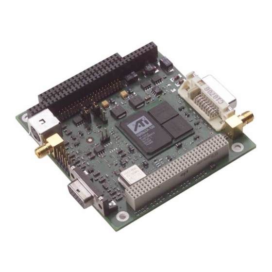
Page 10: Connector And Jumper Description
DIGITAL-LOGIC AG MSMVA104+ Manual V1.0C ONNECTOR AND JUMPER DESCRIPTION Product view The following picture shows a front view from MSMVA104+ Version 0.1. The connector type and signal connections are further explained in section 4.2 Figure 4.1a: Interface connectors on MSMVA104+... - Page 11 DIGITAL-LOGIC AG MSMVA104+ Manual V1.0C LVDS Type Header 40 (2mm intervals) Reference Type Molex MicroCross Digital/Analogue Reference TV-Out (CVBS) Type SMB Coax Reference TV-Out (S-Video) Type Mini-DIN 4 Reference Video-In (CVBS) (not implemented on Version 0.2) Type SMB Coax Reference Video-In (S-Video) (not implemented on Version 0.2)
-
Page 12: Lvds Connector Signals
DIGITAL-LOGIC AG MSMVA104+ Manual V1.0C 4.2.1 LVDS connector signals The following table provides the pin to pin connection to the the LVDS connector J4. The figure with SMD shows the actual pin numbering with a total of 40 pins. Index (L or U) used with LVDS signals refers to the use of dual channel LVDS. -
Page 13: Crt2 Connector Signals
DIGITAL-LOGIC AG MSMVA104+ Manual V1.0C 4.2.2 CRT2 connector signals The following table shows the signals that are present on the CRT2 connector J1. Figure with SMD Top view shows the actual signal connection to the connector J1. J1 Pin Signal... -
Page 14: Dvi Connector Signals
DIGITAL-LOGIC AG MSMVA104+ Manual V1.0C 4.2.4 DVI connector signals For a mechanical front view of the connector, just consult next section. P2 Pin Signal P2 Pin Signal TX2- TX2+ SHIELD_GND No connection No connection DDC_SCL DDC_SDA VSYNC TX1- TX1+ SHIELD_GND... -
Page 15: Jumper Descriptions
DIGITAL-LOGIC AG MSMVA104+ Manual V1.0C Jumper descriptions This chapter provides description for all the jumper present on MSMVA104+. The default factory position is highlighted in red. 4.3.1 J6: LCD Bias power select. (2-jumper) J6 Pin Open J6 Pin Closed VCCLCD: 5V VCCLCD: 3.3V... -
Page 16: Pci Settings Resistor Jumpers
DIGITAL-LOGIC AG MSMVA104+ Manual V1.0C 4.3.7 PCI settings resistor jumpers PCI settings for MSMVA104+ which enable slot position configuration (slot0, slot1 and slot2 positions) 4.3.7.1 PCI_IDSEL resistor jumpers Only one of these resistor should be populated to select IDSEL line. -
Page 17: Dimensions, Connector And Jumper Locations
The following two figures show the dimension of the MSMVA104+ V0.2, standard PC/104+ product. For the connector references please consult the dedicated chapter 4. For additional information about connector positions, please contact Digital-Logic AG. Since 03/2006 the MSMVA is delivered with a active cooler. The max. high with the cooler is 19.33mm. -
Page 18: Driver And Software
6.1.1 Possible display by first boot With M7 SVGA.BIN to be found on ati product CD from Digital-logic (to be found on CD:\bios\ati_vga_bios), you may boot using a sole TV Display Possible display combinations while booting (using pre programmed BIOS) are listed... - Page 19 DIGITAL-LOGIC AG MSMVA104+ Manual V1.0C 6.1.3.1 ATI Displays Tab The ATI Displays tab provides the multi monitor features. Here you can enable/disable display devices and swap the assignment of Primary and Secondary displays. Enabling/Disabling Secondary Displays 1 Access the Windows® Control Panel. Doubleclick Display.
- Page 20 DIGITAL-LOGIC AG MSMVA104+ Manual V1.0C Dynamic Display Reassignment You can change the assignment of your Primary and Secondary display on the fly, without rebooting. However, before you can change the assignment of the Primary display, at least one Secondary display must be enabled, and Extended Desktop mode must be enabled.
- Page 21 DIGITAL-LOGIC AG MSMVA104+ Manual V1.0C ATI Color Tab 6.1.3.2 The ATI Color tab is used to adjust the color settings.You can change the red, green and blue display colors. Desktop brightness and Game Gamma (brightness) can also be changed.
- Page 22 DIGITAL-LOGIC AG MSMVA104+ Manual V1.0C ATI Options Tab 6.1.3.3 The ATI Options tab provides detailed driver information and access to the card’s specifications. You can also enable or disable the ATI taskbar icon.
- Page 23 DIGITAL-LOGIC AG MSMVA104+ Manual V1.0C ATI Overlay Tab 6.1.3.4 The ATI Overlay tab allows you to configure the brightness, contrast, saturation, hue and gamma properties of your video overlay. Video Overlay Video overlay allows for the viewing of full-motion video on your PC. However, there is only one video overlay, which is only available on the Primary display.
-
Page 24: Direct 3D Control Panel
DIGITAL-LOGIC AG MSMVA104+ Manual V1.0C 6.1.4 Direct 3D Control Panel Using this tab, gamers can tweak the settings of their Direct 3D® games. Main and Custom Settings 6.1.4.1 In the Main Settings you can maximize overall performance by moving the slider to the left, or you can... - Page 25 DIGITAL-LOGIC AG MSMVA104+ Manual V1.0C...
- Page 26 DIGITAL-LOGIC AG MSMVA104+ Manual V1.0C...
- Page 27 DIGITAL-LOGIC AG MSMVA104+ Manual V1.0C 6.1.4.2 Direct 3D Compatibility Settings...
- Page 28 DIGITAL-LOGIC AG MSMVA104+ Manual V1.0C...
-
Page 29: Opengl Control Panel
DIGITAL-LOGIC AG MSMVA104+ Manual V1.0C 6.1.5 OpenGL Control Panel Using this tab, gamers can tweak the settings of their OpenGL® games. 6.1.5.1 Main and Custom Settings In the Main Settings you can maximize overall performance by moving the slider to the left, or you can... - Page 30 DIGITAL-LOGIC AG MSMVA104+ Manual V1.0C...
- Page 31 DIGITAL-LOGIC AG MSMVA104+ Manual V1.0C...
-
Page 32: Special Note About Tv-Out
DIGITAL-LOGIC AG MSMVA104+ Manual V1.0C 6.1.5.2 OpenGL Compatibility Settings 6.1.6 Special note about TV-Out How To Enable/Disable The TV Display 1 Access the Windows® Control Panel. Doubleclick Display. 2 Click on the Settings tab and then the Advanced... button. 3 Click on the ATI Displays tab. Click on the TV button. - Page 33 DIGITAL-LOGIC AG MSMVA104+ Manual V1.0C Using and Adjusting TV Out For information about how to use TV display, right click the ATI taskbar icon, point to Help, then point to ATI Television Display. How TV Display Cannot Be Used A TV cannot be left connected to the graphics card if two analog monitors are connected to your RADEON card, even if the TV is off and not enabled in the software.
- Page 34 DIGITAL-LOGIC AG MSMVA104+ Manual V1.0C To Increase the Horizontal Size 1 Access the Windows® Control Panel. Doubleclick Display. 2 Click on the Settings tab and then the Advanced... button. 3 Click on the ATI Displays tab. 4 Click on the TV button.
-
Page 35: 6.2 Linux
MSMVA104+ Manual V1.0C 6.2 Linux This document describes how to setup the Digital-Logic MSMVA104+ board under Linux. An example configuration for a dualhead (DVI + CRT) setup is listed. This has been tested with kernel version 2.6.10 and Xorg version 6.8.1. The DVI and CRT outputs of the MSMVA104+ board are supported by the radeon driver which is part of Xorg. - Page 36 DIGITAL-LOGIC AG MSMVA104+ Manual V1.0C EndSection Section "Device" Identifier "VideocardMSMVA104p" Driver "radeon" VendorName "DLAG" BoardName "MSMVA104p" Option "MonitorLayout" "TMDS, CRT" Option "MergedFB" "true" Option "CRT2HSync" "28 - 64" Option "CRT2VRefresh" "48 - 75" Option "CRT2Position" "RightOf" Option "MetaMode" "2048x768, 1600x600"...
-
Page 37: Graphic Modes
DIGITAL-LOGIC AG MSMVA104+ Manual V1.0C RAPHIC MODES 2D Graphic Modes... - Page 38 DIGITAL-LOGIC AG MSMVA104+ Manual V1.0C...
- Page 39 DIGITAL-LOGIC AG MSMVA104+ Manual V1.0C...
-
Page 40: Video Bios Update
DIGITAL-LOGIC AG MSMVA104+ Manual V1.0C BIOS U IDEO PDATE ATIflash utility The file atiflash.exe can be used in conjunction with extension to perform some diagnostics or to update the video BIOS from the adapter. Depending on the atiflash.exe tool version, the message displayed could vary. -
Page 41: Setting Up The System
DIGITAL-LOGIC AG MSMVA104+ Manual V1.0C 8.1.2 Setting up the system Prepare a DOS boot floppy disk with following files on it: ATI.ROM ATIFLASH.CFG ATIFLASH.EXE DOS4GW.EXE First perform a dump from the original BIOS using command atiflash –s 0 original.rom The utility then displays a small list with file name, size and checksum. -
Page 42: Index
DIGITAL-LOGIC AG MSMVA104+ Manual V1.0C NDEX BIOS ..............6 Jumper locations ..........17 Bus..............6 Linux ...............35 Color Tab ............21 LVDS ............7, 11 Contrast ............34 Control Panel ..........18 Controller ............6 Multimedia ............8 Dimensions ............ 17 Direct 3D Tab..........24 OpenGL Tab...........29...
Need help?
Do you have a question about the MICROSPACE MSMVA104+ and is the answer not in the manual?
Questions and answers