Table of Contents
Advertisement
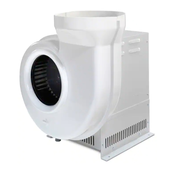
Intelli-Sense™ Multi-Speed
Coated Steel Models
Complete Intelli-Sense MSB
Blower with Controls
All 50/60 Hz
CS 10"
7061110-115v, -20-230v
CS 12"
7061112-115v, -22-230v
Fiberglass Models
Complete Intelli-Sense MSB
Blower with Controls
All 50/60 Hz
FRP 10"
7181810-115v, -20-230v
FRP 12"
7181812-115v, -22-230v
PVC Models
Complete Intelli-Sense MSB
Blower with Controls
All 50/60 Hz
PVC 10"
7183410-115v, -20-230v
PVC 12"
7183412-115v, -22-230v
Blowers
Intelli-Sense MSB Blower – No Controls (used for
replacement or Integrated Intelli-Sense Hoods)
All 50/60 Hz
7061111-115v, -21-230v
7061113-115v, -23-230v
Intelli-Sense MSB Blower – No Controls (used for
replacement or Integrated Intelli-Sense Hoods)
All 50/60 Hz
7181811-115v, -21-230v
7181813-115v, -23-230v
Intelli-Sense MSB Blower – No Controls (used for
replacement or Integrated Intelli-Sense Hoods)
All 50/60 Hz
7183411-115v, -21-230v
7183413-115v, -23-230v
Advertisement
Table of Contents

Subscribe to Our Youtube Channel
Summary of Contents for Labconco Intelli-Sense CS 10
- Page 1 Intelli-Sense™ Multi-Speed Blowers Coated Steel Models Intelli-Sense MSB Blower – No Controls (used for Complete Intelli-Sense MSB Blower with Controls replacement or Integrated Intelli-Sense Hoods) All 50/60 Hz All 50/60 Hz CS 10" 7061110-115v, -20-230v 7061111-115v, -21-230v CS 12" 7061112-115v, -22-230v 7061113-115v, -23-230v Fiberglass Models Intelli-Sense MSB Blower –...
- Page 2 Warranty Labconco Corporation provides a warranty to the original buyer for the repair or replacement of parts and reasonable labor as a result of normal and proper use of the equipment with compatible chemicals. Broken glassware and maintenance items, such as filters, gaskets, light bulbs, finishes and lubrication are not warranted.
-
Page 3: Table Of Contents
ORIGINAL INSTRUCTIONS ABLE ONTENTS CHAPTER 1: INTRODUCTION About This Manual Typographical Conventions CHAPTER 2: PREREQUISITES Location Requirements Mounting Support Requirements Electrical Power Requirements Controls Wiring Space Requirements CHAPTER 3: GETTING STARTED Unpacking Your Blower Install Blower on a Supporting Structure Adjust Blower Outlet Orientation Install Exhaust Run with Vibration Dampers Connect Blower Inlet for Coated Steel Blowers... - Page 4 CHAPTER 7: MODIFYING YOUR BLOWER, CALCULATING STATIC PRESSURE LOSS, AND BLOWER SIZING Airflow Monitors for Fume Hoods Two Main Blower Modifications Additional Modifications by Adding Ductwork Accessories Blower Sizing Example Sizes and Pressure Losses in Thermoplastic Duct Typical Fume Removal System Thermoplastic Duct Duct Couplings, Female Duct Couplings, Male...
-
Page 5: Chapter 1: Introduction
HAPTER NTRODUCTION Congratulations on your purchase of a Labconco Intelli-Sense Multi-Speed Blower (MSB). Your MSB with electronically commutated motor (ECM) has been specifically engineered to meet the demanding requirements of most laboratory ventilation situations associated with fume hood and enclosure exhaust. The outside steel housing of the blower encloses the UL listed ECM motor, shaft, junction box wiring, and bearings. -
Page 6: About This Manual
Original instructions Chapter 1: Introduction position systems can reduce air flow (CFM) by 50-70% per year. For example, a 6- ft fume hood operating 24 hours a day at 100fpm (735 CFM at $7/CFM/Yr) at the 18-in sash height at constant volume can cost $5145 per year to operate, but with a MSB used 4 hours per day and the remaining 20 hours a day in standby mode would cost only $2578 per year to operate, saving $2567 per hood annually. -
Page 7: Typographical Conventions
Original instructions Chapter 1: Introduction Chapter 8: Troubleshooting contains a table of situations you may encounter while using your blower including the probable causes of the problems and suggested corrective actions. Appendix A: Blower Replacement Parts contains labeled diagrams of all of the components of the blowers. - Page 8 Original instructions Chapter 1: Introduction The FRP icon indicates the text is specific to the Fiberglass Blower. The PVC icon indicates the text is specific to the PVC Blower. CAUTION – See Manual. When this symbol is on the unit it indicates a caution that is detailed in this manual.
-
Page 9: Chapter 2: Prerequisites
HAPTER REREQUISITES Before you install your blower, you need to prepare your site for installation. A dedicated source of electrical power must be located near the installation site. Carefully read this chapter to learn: The location requirements for your installation site. ... -
Page 10: Mounting Support Requirements
You must provide vibration isolators, vibration mounting pads, and/or a roof curb support for proper mounting of the blower. Vibration isolators or vibration mounting pads are available from many sources such as a local industrial supply company. Labconco recommends supporting the blower with 5/16" diameter mounting hardware. Electrical Power Requirements Please refer to the wiring diagrams in Appendix C. -
Page 11: Chapter 3 Getting Started
Commerce the carrier. Commission rules require DO NOT RETURN GOODS WITHOUT THE PRIOR that claims be AUTHORIZATION OF LABCONCO. UNAUTHORIZED filed with the delivery carrier RETURNS WILL NOT BE ACCEPTED. within fifteen (15) days of delivery. Product Service 1-800-522-7658... -
Page 12: Install Blower On A Supporting Structure
The supporting structure is custom for each installation. Labconco recommends supporting the blower with 5/16" diameter mounting hardware. See Appendix B: Blower Dimensions for appropriate mounting hole locations for your particular blower. -
Page 13: Install Exhaust Run With Vibration Dampers
Original instructions Chapter 3: Getting Started Install the Exhaust Run with Vibration Dampers Rubber isolation sleeves may be used in your exhaust duct run prior to entering the blower inlet. These isolation sleeves dampen vibration that is being generated by the blower and decrease noise level at the fume hood. -
Page 14: Connect Pvc Blower Drain
Original instructions Chapter 3: Getting Started 12" PVC Blowers feature a 12-3/8" OD inlet ring, which is suitable for use with 12-inch diameter PVC ductwork. The 12-inch diameter PVC ductwork will fit over the inlet ring on the blower and should be fastened in position by sheet metal screws into the fiberglass ring. - Page 15 Structural support is connected to C-clamp coupler. Note: Duct diameters, duct materials, and heights change and Labconco does not carry the structural supports or guy wires. Good Installation – Picture 2...
- Page 16 Typical structural frame to support exhaust duct and resist wind damage. Typical 3-piece turnbuckle connected to structural frame. Five Typical Blowers Note: Duct diameters, duct materials, and heights change and Labconco does not carry the structural supports or guy wires. Product Service 1-800-522-7658...
-
Page 17: For Coated Steel Blowers
Transition Adaptor, Labconco part number 4722401, adapts the outlet connection to accept 10-inch diameter PVC ductwork Transition Adaptor. Labconco part number 4722400 adapts the outlet on these blowers to accept 8-inch diameter PVC ductwork. 12" Coated Steel Blowers include a 13-1/2" by 7" rectangular outlet. Transition Adaptor, Labconco part number 7003400, adapts the outlet of these blowers to accept 12-inch diameter PVC ductwork. -
Page 18: Connect To The Electrical Supply Source
Original instructions Chapter 3: Getting Started Connect to the Electrical Supply Source The main electrical power supply connection for the MSB is made directly at the junction box underneath the outer weather cover and below the ECM motor. Refer to wiring detail and wiring diagrams in Appendix C. Remove the weather cover from the MSB and wire directly to the power wires inside the outside junction box located beneath the ECM motor. -
Page 19: Modify The Fume Hood Controls And Install The
Modify the Fume Hood Controls and Install the MSB Blower Control Box Labconco Intelli-Sense Blowers require control circuitry to vary the speed and set up the fume hood for two or three speed operation. If desired, the MSB can still be set up for simple ON/OFF operation. - Page 20 Original instructions Chapter 3: Getting Started 5. Run the MSB Control Box Power Cable with the IEC inlet from the control box to the junction box on the fume hood and connect to the fume hood light circuit per wiring detail and wirings diagram in Appendix C. 6.
- Page 21 Original instructions Chapter 3: Getting Started Control Box Fume Hood Junction Box Figure 3-2 Top View of Typical Isometric View of MSB Control Box Product Service 1-800-522-7658...
- Page 22 Original instructions Chapter 3: Getting Started Control Figure 3-3 3' Installation Location Control Figure 3-4 4' Installation Location Product Service 1-800-522-7658...
- Page 23 Original instructions Chapter 3: Getting Started Control Figure 3-5 5' Installation Location Control Figure 3-6 6' Installation Location Product Service 1-800-522-7658...
- Page 24 Original instructions Chapter 3: Getting Started Control Figure 3-7 7' Installation Location Control Figure 3-8 8' Installation Location Product Service 1-800-522-7658...
-
Page 25: Adjust Fan Speed And Confirm Performance
Original instructions Chapter 3: Getting Started Adjust the Fan Speeds and Confirm the Performance of your Multi-Speed Blower/ Hood System The MSB fan speeds need to be adjusted in the field to allow the hood to operate at the proper face velocity. In order to adjust the blower to the proper speeds, refer to the diagram in Figure 3-9 and follow the procedure below. - Page 26 Original instructions Chapter 3: Getting Started Figure 3-9 Adjust the Fan Speeds Product Service 1-800-522-7658...
-
Page 27: Chapter 4: Performance Data & Safety Precautions
HAPTER ERFORMANCE ATA AND AFETY RECAUTIONS Specifications and Performance Data The specifications and performance data for your particular model are listed in detail in Chapter 4 and sub-grouped by Coated Steel, Fiberglass, and PVC Blowers. Refer to Appendix D to view the effect damper position has on performance. -
Page 28: Blower Curves
Original instructions Chapter 4: Performance Data & Safety Precautions Models 70611-10, -11, -20, -21 120- 240 Volts 10.0 Amps 1 HP Blower Performance Curve with 10" Coated Steel inlet 2.25 1750 1.75 1500 Optimum 1.25 Blower Performance NOTE 1250 0.75 1000 Note: Ambient Temperatures 0.25... - Page 29 Original instructions Chapter 4: Performance Data & Safety Precautions 2.25 Models 70611-12, -13, -22, -23 120- 240 Volts 10.0 Amps 1 HP 1250 RPM Blower Performance Curve with 12" Coated Steel inlet 1.75 Note 1000 1.25 Optimum Blower Performance 0.75 Note: Ambient Temperatures 0.25 Inside Motor Housing Greater...
- Page 30 Original instructions Chapter 4: Performance Data & Safety Precautions Models 71818-10, -11, -20, -21 120- 240 Volts 10.0 Amps 1 HP Blower Performance Curve with 10" FRP inlet 1.75 Optimum 1800 Blower 1.25 Performance 1750 1500 0.75 NOTE 1250 1000 Note: Ambient Temperatures 0.25 Inside Motor Housing Greater...
- Page 31 Original instructions Chapter 4: Performance Data & Safety Precautions 2.25 Models 71818-12, -13, -22, -23 120- 240 Volts 10.0 Amps 1 HP Blower Performance Curve with 12" FRP inlet 1500 1.75 See Note 1400 1300 1.25 1250 RPM Optimum Blower Performance 0.75 1000...
- Page 32 Original instructions Chapter 4: Performance Data & Safety Precautions Models 71834-10, -11, -20, -21 120- 240 Volts 10.0 Amps 1 HP Blower Performance Curve with 10" PVC inlet 1.75 Optimum 1800 RPM Blower 1.25 Performance 1750 RPM 1500 RPM 0.75 1250 RPM NOTE 1000 RPM...
- Page 33 Original instructions Chapter 4: Performance Data & Safety Precautions 2.25 Models 71834-12, -13, -22, -23 120- 240 Volts 10.0 Amps 1 HP Blower Performance Curve with 12" PVC inlet 1500 1.75 See Note 1.25 1250 RPM Optimum Blower Performance 0.75 1000 Note: Ambient Temperatures 0.25...
-
Page 34: Safety Precautions
Original instructions Chapter 4: Performance Data & Safety Precautions NOTE: FOR A COMPLETE PERSPECTIVE OF YOUR MSB, REFER TO APPENDIX A REPLACEMENT PARTS. Safety Precautions Before attempting any service and/or maintenance on your blower, always disconnect the blower motor from its power source to prevent possible injury. -
Page 35: Chapter 5: Using Your Blower
For night set back to save energy, fully lower the fume hood sash and select the lowest switch setting. Always monitor your airflow constantly with a fume hood airflow monitor. For best results, use Labconco’s Guardian Digital Airflow Monitor and order from Chapter 7. - Page 36 Original instructions Chapter 5: Using Your Blower Product Service 1-800-522-7658...
-
Page 37: Chapter 6: Maintaining Your Blower
HAPTER AINTAINING LOWER Now we will review the suggested maintenance schedule and the common service operations necessary to maintain your blower for peak performance. Only trained and experienced certification technicians should perform some of the service operations after the blower has been properly decontaminated. -
Page 38: Bearings
Original instructions Chapter 6: Maintaining Your Blower Bearings The pillow block bearings on your blower are factory sealed and lubricated. Under normal operation, no further lubrication is required. Excessive lubricating may cause damage to the bearing seal and significantly shorten the life span of the bearing. -
Page 39: Airflow Monitors For Fume Hoods
HAPTER ODIFYING LOWER, ALCULATING TATIC RESSURE OSS, AND LOWER IZING Airflow Monitors for Fume Hoods Guardian™ Airflow Monitors continuously monitor face velocity through the fume hood opening and should always be used with Intelli-Sense Multi-Speed Blowers. Guardian™ Airflow Monitors Sense and alert the operator to low airflow conditions. From the monitor’s face plate, the user can easily select and calibrate a set point between 30 and 250 fpm using a velocity meter and a screwdriver. -
Page 40: Two Main Blower Modifications
Then the blower can be sized properly from the total equivalent resistance for your exhaust system. Blower Sizing Example: You have selected a Labconco Protector Premier 48 Laboratory Hood at 100 fpm and 725 CFM. The static pressure of the Protector Premier 48 at 100 fpm is 0.22". -
Page 41: Sizes And Pressure Losses In Thermoplastic Duct
Original instructions Chapter 7: Modifying Your Blower duct, two 90° elbows and one zero pressure weathercap to adequately exhaust the chemical fumes. You will be handling low to moderately corrosive materials, so you have selected a Coated Steel Blower. The information following for the 90° elbow tells you that each 90°, 12" diameter elbow has the equivalent resistance of 25 feet of straight duct. -
Page 42: Typical Fume Removal System
Chapter 7: Modifying Your Blower Typical Fume Removal System This diagram details the many components that are needed to complete a typical fume removal system. All of these components as well as others are available from Labconco. Zero Pressure Weathercap Thermoplastic Duct... -
Page 43: Thermoplastic Duct
Original instructions Chapter 7: Modifying Your Blower Thermoplastic Duct PVC exhaust duct is Type 1, unplasticized, schedule 40, lightweight and corrosion- resistant. A female duct coupling is required to join two sections. Connections are simple with solvent cement. This rigid duct may be cut without special tools. Comes in 10' lengths. -
Page 44: Thermoplastic Duct Reducers
Original instructions Chapter 7: Modifying Your Blower Thermoplastic Duct Reducers PVC coupling type reducers are designed for connecting thermoplastic duct of different diameters. Compare your blower inlet size with your duct size to see if one is necessary. Nominal Size/Inches 8x10 10x12 12x16... -
Page 45: Flexible Duct Connections
48893 Shipping Wt./lbs. T and Y Connections PVC fittings shaped in T and Y configurations are compatible with thermoplastic duct. End connections receive PVC pipe directly. Contact Labconco for help in sizing blowers with these accessories. Nominal Diameter/Inches 10x10x12 Catalog Number 56304 T’s... -
Page 46: Accessories For Basic 47 Hoods
Original instructions Chapter 7: Modifying Your Blower Accessory for Basic 47 Hoods Exhaust Transition Adaptor The exhaust transition adapts to 7" and 10" rectangular outlet on Basic 47 Hoods, model series 22473 and 22475, to receive 10" diameter PVC duct. Nominal Diameter/Inches Catalog Number 22648... -
Page 47: Backdraft Dampers
Original instructions Chapter 7: Modifying Your Blower Backdraft Dampers Designed for use in buildings under negative pressure to keep outside air from entering the laboratory through the hood ventilation system. Damper is weighted to stay in down/resting position when the hood is not in use, and rises from the airflow exhausting when the blower is on. - Page 48 Original instructions Chapter 7: Modifying Your Blower Product Service 1-800-522-7658...
-
Page 49: Chapter 8: Protector I-S Hood
Appendix E are sold separately and are not sold by Labconco. The Protector I-S Hood is primarily used for small hood projects when the number of fume hoods cannot justify a complete variable airflow volume system or VAV. - Page 50 (Appendix E), duct sensors, or hood exhaust volume controls are not included. The variety of room controls MUST BE selected by the building controls engineering department. Note: Room controls are not sold by Labconco. In typical environments the room controls are set to a negative pressure with a range of -0.01"...
- Page 51 Original instructions Chapter 8: Protector I-S Hood Left side upper limit switch wired for high speed and set to activate with sash raised 20" above work surface. The upper limit switch can be lowered in 1" increments between 15" and 20". Intelli-Sense Control Box powered up and functional without lights.
- Page 52 Original instructions Chapter 8: Protector I-S Hood Black wire to normally open. Left side lower limit switch wired for low speed. Red wire to common. Product Service 1-800-522-7658...
- Page 53 Original instructions Chapter 8: Protector I-S Hood Back of airflow Power to air monitor. monitor. Airflow monitor in-line sensor, air pathway, and wiring to monitor. Night setback lower switch shown on right. Switch is wired to normally open and common terminals, and wired to air monitor input I/P1.
- Page 54 Original instructions Chapter 8: Protector I-S Hood Front of airflow monitor showing “SETBACK” when sash is closed. Product Service 1-800-522-7658...
- Page 55 Original instructions Chapter 8: Protector I-S Hood Sensor wiring in to air monitor. Back of airflow monitor night setback switch wiring to I/P1 for Input 1. Power in to air monitor. Product Service 1-800-522-7658...
-
Page 56: Chapter 9: Troubleshooting
HAPTER ROUBLESHOOTING Refer to the following table if your blower fails to operate properly. If the suggested corrective actions do not solve your problem, contact Labconco for additional assistance. PROBLEM CAUSE CORRECTIVE ACTION Wires not connected Check connection of switches. - Page 57 Original instructions Chapter 9: Troubleshooting PROBLEM CAUSE CORRECTIVE ACTION Fume hood has Have fume hood re-certified and Contamination outside of fume hood. improper face check remote blower exhaust velocity system. Hood should have average face velocity of 60-100 fpm depending on application. Remote blower has Improper motor Review Chapter 2: Prerequisites...
- Page 58 Original instructions Chapter 9: Troubleshooting Product Service 1-800-522-7658...
-
Page 59: Appendix A: Blower Replacement Parts
PPENDIX LOWER EPLACEMENT ARTS IRING HOWN The following replacement parts are organized for Intelli-Sense MSB’s for low pressure coated steel, low pressure fiberglass, and low pressure PVC. See next page for illustrations. Description – Roof Blower Components Item Quantity Part No. 7117101 Shaft Coupler 1889012... - Page 60 Original instructions Appendix A: Blower Replacement Parts Description – Roof Blower Components Item Quantity Part No. 1860500 Flanged Pillow Block Bearing 5/8" Bore Screw – Cap Hex Head 3/8 – 16 x 0.75" SS 1881712 1910018 Lockwasher 3/8 9816700 J-Box, Blower 9816800 Cover, J-Box Blower 4450100...
- Page 61 Original instructions Appendix A: Blower Replacement Parts Not Shown 8A Cable, Manual Blower Switch to MSB Control Box 8B Cable, Automatic Limit Switches to MSB Control Box Not Shown 13, 14, 15 Not Shown Not Shown Not Shown 11A Blower Switch, Manual 11C Limit Switch, Automatic Figure A-1 Product Service 1-800-522-7658...
-
Page 62: Appendix B Blower Dimensions
PPENDIX LOWER IMENSIONS Product Service 1-800-522-7658... - Page 63 Original instructions Appendix B: Blower Dimensions Product Service 1-800-522-7658...
- Page 64 Original instructions Appendix B: Blower Dimensions Product Service 1-800-522-7658...
-
Page 65: Appendix C: Blower Environmental Conditions
PPENDIX LOWER NVIRONMENTAL ONDITIONS, IRING ETAIL & IRING IAGRAMS Environmental Conditions Maximum altitude: 9843 feet (3000 meters). Ambient temperature range: -30° to 130°F (-34° to 54°C). Main supply voltage fluctuations not to exceed ±10% of the nominal voltage. - Page 66 Original instructions Appendix C: Blower Environmental Conditions & Wiring Diagrams Wiring Detail (Belden 9940, 22 GA, 4 conductor shielded or equal) Alternate: Cable harness to limit switches for automatic operation. See Chapter 8. Product Service 1-800-522-7658...
- Page 67 Original instructions Appendix C: Blower Environmental Conditions & Wiring Diagrams 115V Wiring Diagram – Manual Operation 230V Wiring Diagram – Manual Operation Product Service 1-800-522-7658...
- Page 68 Original instructions Appendix C: Blower Environmental Conditions & Wiring Diagrams 115V Wiring Diagram – Automatic Operation 230V Wiring Diagram – Automatic Operation Product Service 1-800-522-7658...
-
Page 69: Appendix D: Typical Intelli-Sense Operating Curve
PPENDIX YPICAL NTELLI ENSE LOWER PERATING URVE Damper 50% Open (Red) • High Data Point, H1 895 CFM, 1.8" S.P., 1250 RPM • Medium Data Point, M1 675 CFM, 1.0" S.P., 895 RPM • Low Data Point, L1 260 CFM, 0.12" S.P., 330 RPM Damper 75% Open (Green) •... - Page 70 Original instructions Appendix D: Typical Intelli-Sense Blower Operating Curve Product Service 1-800-522-7658...
-
Page 71: Appendix E: Typical Laboratory Controls With
PPENDIX YPICAL ABORATORY ONTROLS NDIVIDUAL NTELLI- ENSE LOWERS Product Service 1-800-522-7658... -
Page 72: Appendix F: Typical Perchloric Acid Hood Installation Diagram
PPENDIX YPICAL ERCHLORIC NSTALLATION IAGRAM Product Service 1-800-522-7658...
Need help?
Do you have a question about the Intelli-Sense CS 10 and is the answer not in the manual?
Questions and answers