Table of Contents
Advertisement
Quick Links
Advertisement
Table of Contents

Related Manuals for LMI chroma+scan 3 00 Series

Summary of Contents for LMI chroma+scan 3 00 Series
- Page 1 chroma+scan 3x00 Document Version 4.11.12.30...
- Page 2 This document, submitted in confidence, contains proprietary information which shall not be reproduced or transferred to other documents or disclosed to others or used for manufacturing or any other purpose without prior written permission of LMI Technologies Inc. No part of this publication may be copied, photocopied, reproduced, transmitted, transcribed, or reduced to any electronic medium or machine readable form without prior written consent of LMI Technologies, Inc.
-
Page 3: Table Of Contents
Table of Contents Table of Contents ......................3 Laser Safety ......................6 General Information ..................6 Laser Classification ................... 7 1.2.1 Laser Classes .................... 7 1.2.2 User Precautions and OEM Responsibilities ..........8 1.2.3 Class 3B/lllb OEM Responsibilities ............. 8 Requirements for Laser Systems Sold or Used In the USA ...... - Page 4 Vision ......................26 Tracheid ......................26 High Scan Rates ..................... 26 Temperature Compensated Ranges ............... 26 chroma+scan 3x00 Sensor Specifications .............. 27 Models ......................27 Performance ....................28 Specifications ....................28 Scan Zone....................... 29 5.4.1 chroma+scan 3350 Scan Zone ..............29 5.4.2 chroma+scan 3155/3250 Scan Zone ............
- Page 5 7.2.7.3 Sensor Health Indicators ..............66 7.2.8 Event Channel ..................67 File Formats ....................68 7.3.1 Server Settings ..................68 7.3.2 Calibration Target ..................75 7.3.3 Calibration Output ..................76 Modes and Messages ..................77 7.4.1 Free Mode ....................78 7.4.2 Calibration Mode ..................
-
Page 6: Laser Safety
Section 1 1 Laser Safety 1.1 General Information The laser light sources used in LMI Sensors are semiconductor lasers emitting visible light. LMI Laser Sensors have a 2/ll, 3R/llla or 3B/lllb classification depending on model. Class 2/ll and 3R/llla sensors are referred to as “products” indicating that they fully comply with the standards relating to laser products specified in IEC 60825-1 and U.S. -
Page 7: Laser Classification
1. International Standard IEC 60825-1 (2001-08) Consolidated edition, Safety of laser products – Part 1: Equipment classification, requirements and user’s guide 2. Technical Report TR 60825-10, safety of laser products – Part 10. Application guidelines and explanatory notes to IEC 60825-1 3. -
Page 8: User Precautions And Oem Responsibilities
1.2.3 Class 3B/lllb OEM Responsibilities LMI Technologies has filed reports with the FDA to assist the OEM in achieving certification of their laser products. The OEM can reference these reports by an accession number that will be provided upon request. - Page 9 A permanently attached method of preventing human access to the laser radiation other than switches, power connectors or key control must be employed. On some LMI laser sensors, the beam attenuator is supplied with the sensor as an integrated mechanical shutter.
-
Page 10: Requirements For Laser Systems Sold Or Used In The Usa
1.3 Requirements for Laser Systems Sold or Used In the USA The OEM’s laser system which incorporates laser components or laser products manufactured by LMI Technologies requires certification by the FDA. It is the responsibility of the OEM to achieve and maintain this certification. -
Page 11: Proper Handling And Precautions
2.1.2 Shielded Cable LMI Technologies recommends the use of shielded cables in all environments to ensure isolation from electrical noise. The shield should be electrically connected to both the sensor housing through the connector housing and to the electrical box containing either the Master (network systems) or the power supply (standalone sensors). -
Page 12: Uninterruptible Power Supply (Ups)
2.1.4 Uninterruptible Power Supply (UPS) To maximize the life of the sensor, LMI Technologies recommends the use of an on-line double-conversion UPS whenever the quality of the electrical supply to the system is poor. This includes but is not limited to when the electrical supply: •... -
Page 13: Getting Started
More detailed information is given in the sections that follow this "Getting Started" guide. 3.1 Components LMI Technologies provides chroma+scan 3155, 3250, or 3350 sensors, a Master and information on cables to connect the Sensors, Master, and user provided equipment. -
Page 14: Sensors
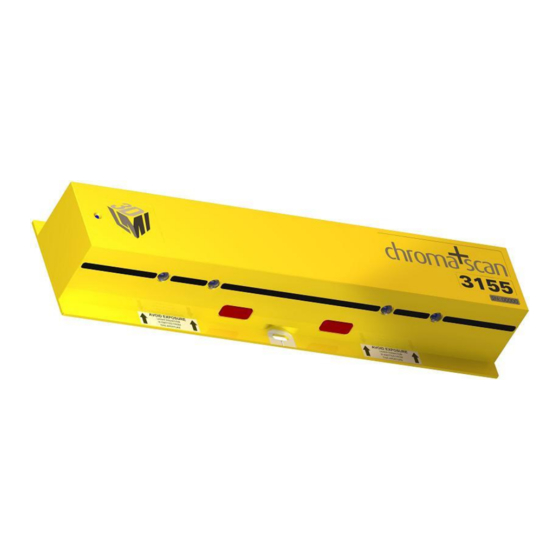
3.1.1 Sensors chroma+scan 3155 chroma+scan 3250 chroma+scan 3350... -
Page 15: Master
3.1.3 Cables Network Cordset The above cable is available from LMI and/or its suppliers. Also required are standard CAT5e Gigabit Ethernet cables (RJ45 connectors) to connect the user Station PC to the client computer and the Sensor network GigE switch. -
Page 16: Station Computer
recommended that a 16 sensor system uses a +48V power supply capable of delivering 16A. The Phoenix QUINT series power supplies are DIN rail mounted devices that can be connected in parallel to increase the overall available power. +48 VDC Model: QUINT-PS-100-240AC/48DC/10 Order number:... -
Page 17: Client Computer
Ethernet port to communicate with the FireSync Station. The client Interface to the Station is OS independent. However, Windows XP or Windows 7 (32-bit/64-bit) is required on this computer in order to install and run LMI’s FireSync Client demonstration application. 3.1.7 Gigabit Ethernet Switch The user must provide a suitable Gigabit Ethernet Switch for the Sensor network. -
Page 18: Power Supply To Master/Station
The client PC’s IP address will have to be configured to the same subnet as the station’s OUT port: • In the Windows control panel, select “Network Connections” • Double-click on the name of the connection being used • Click “Properties”, and double-click on “Internet Protocol (TCP/IP)”. This window will show up: •... -
Page 19: Connection Guidelines
The FireSync Client application is available for Windows, and can be downloaded from the LMI Technologies support website. To begin, download the software and install it on a suitable client machine. The client machine should have an Ethernet adaptor that can be configured for a static IP address and that supports 1000 Mb/s operation. -
Page 20: Connection
3.3.2 Connection After starting FireSync Client, use the Connect (left-most) icon in the toolbar to display the Connect... dialog. To connect to a single server, enter the IP address of the server to which you wish to connect, and then click OK. To connect to multiple servers simultaneously, click the Advanced…... -
Page 21: Server Health
3.3.3 Server Health After connecting, click on the device tree node for each server and then click on the Health visualization tab, as show below. Health indicators can be used to help diagnose a wide variety of conditions. Note that some indicators are updated constantly, while others are only updated if the system is in the Running state. -
Page 22: Sensor Enumeration
3.3.4 Sensor Enumeration Each server can have a Top group of sensors, a Bottom group of sensors, or both. Use the pull-down lists in a Server Setup tab to specify the number of sensors in each group. When the number of sensors in either group is changed, the number of sensor nodes in the device tree changes accordingly. -
Page 23: Sensor Health
3.3.5 Sensor Health After creating entries for each sensor, click on the device tree node for each sensor and review the Sensor Health visualization tab. As with the server health indicators, some sensor health indicators are updated constantly, while others are only updated if the system is in the Running state. -
Page 24: Sensor Data
3.3.6 Sensor Data To view live laser profile data from a sensor, click on the sensor’s node in the device tree, and then select the Obstructions tab. Press the Start button in the FireSync Client toolbar. The Profile visualization tab will display live laser profile measurements. This display can be used in conjunction with a stationary or moving target to verify that laser profiling is operating correctly. -
Page 25: Product Overview
3250 system offers tracheid measurements at 500 Hz and profile sampling at 2500 Hz. The sensors are based on LMI's field-proven FireSync platform, which provides a synchronized, scalable, distributed vision processing architecture for building reliable, high performance systems. -
Page 26: True Differential Measurement
camera mounted at an angle to the laser plane acquires images of the light pattern created on the target. These images contain the basic information needed to compute distances to the target. 4.3 True Differential Measurement The chroma+scan 3x00 sensors can be aligned co-planar top-to-bottom and side-to-side down the length of the system. -
Page 27: Chroma+Scan 3X00 Sensor Specifications
Section 5 5 chroma+scan 3x00 Sensor Specifications This section presents sensor specific chroma+scan 3x00 information. It describes the different models, and gives dimensions of the scan zone and sensor. 5.1 Models chroma+scan 3x00 sensors are available in the following models: chroma+scan 3155: 2000 Hz profiler, safety interlocked chroma+scan 3250:... -
Page 28: Performance
5.2 Performance Profile X-Resolution 8.5 mm 0.333 in Profile Z-Resolution 0.127 mm 0.005 in Profile Y-Resolution @ 1m/s (197 fpm) 0.5 mm 0.020 in ( @ 1.25m/s (246 fpm) for chroma+scan 3250) 5.3 Specifications Operating Temperature 0 - 50°C 32 - 122°F (Non-condensing) Input Power +48VDC @ 1A... -
Page 29: Scan Zone
5.4 Scan Zone 5.4.1 chroma+scan 3350 Scan Zone Standoff (SO) 559 mm 22.0 in Measurement Range (MR) 152 mm 6.0 in Field of View (FOV) through entire range 610 mm 24.0 in... -
Page 30: Chroma+Scan 3155/3250 Scan Zone
5.4.2 chroma+scan 3155/3250 Scan Zone Standoff (SO) 508 mm 20.0 in Measurement Range (MR) 203.2 mm 8.0 in Field of View (FOV) through entire range 609.6 mm 24.0 in... -
Page 31: Dimensions And Mounting
5.5 Dimensions and Mounting 5.5.1 chroma+scan 3155 Sensor Dimensions... -
Page 32: Chroma+Scan 3250 Sensor Dimensions
5.5.2 chroma+scan 3250 Sensor Dimensions... -
Page 33: Chroma+Scan 3350 Sensor Dimensions
5.5.3 chroma+scan 3350 Sensor Dimensions... -
Page 34: Cleaning
The sensor can be mounted with either M8 or 5/16" hardware. Provision to adjust the position and orientation of the sensor to align its laser plane with the laser planes of other sensors, above and beside, is highly recommended. This alignment is critical to prevent sensor crosstalk and ensure true differential measurements;... -
Page 35: System
Section 6 6 System 6.1 Overview A chroma+scan 3x00 system consists of some or all of the following components: chroma+scan 3155, 3250 or 3350 sensors FireSync Master 1200 or Master 2400 User-supplied Station PC(s) FireSync Cordsets Power Supply Encoder Client Computer Scanner Frame System Calibration Target Power and Encoder Wiring... -
Page 36: Firesync Master And Station
As a starting point, LMI recommends a quad-core CPU with 2GB of RAM and 2-3 Gigabit Ethernet network adaptors. - Page 37 LMI Technologies recommends the use of a Phoenix Contact, QUINT, 10 Amp power supply (for +48 VDC). The Phoenix QUINT series power supplies are DIN rail mounted devices that can be connected in parallel to increase the overall available power.
-
Page 38: Encoder
6.4 Encoder The user must provide a suitable encoder. The requirements are: • Differential quadrature output (maximum 18 V) • +5 VDC power supply input The encoder interface on the Master provides the following: • X4 quadrature decoding • Maximum 300 kHz count rate •... -
Page 39: Frame Design
6.6 Frame Design The scan frame supports the sensors above and below the chain deck to the maximum size of the boards to be scanned. Typically, there are 10 to 12 sensors mounted above the chain and another 10 to 12 sensors mounted below. This provides complete coverage of the top and bottom surfaces of the boards. -
Page 40: Chroma+Scan 3155/3250 System Configuration
6.6.2 chroma+scan 3155/3250 System Configuration The above configuration of chroma+scan 3155/3250 sensors provides a full 6 inch overlapped scan zone starting from 1 inch below the chainways and extends to 5 inches above the chainways. The extended range of the chroma+scan 3155/3250 sensors provides an additional 2 inches of coverage from the top sensors above this overlapped zone as well as an additional 2 inches below the overlapped zone from the bottom sensors. -
Page 41: System Calibration Target
6.7 System Calibration Target The system calibration target is required to perform a system calibration. This process locates each sensor with respect to a global coordinate system defined relative to the target. For chroma+scan 3350 systems, additional reference holes can be used to calibrate the position of each colour camera along the length of the system. -
Page 42: Software
Section 7 7 Software This section describes the software interfaces to a chroma+scan 3x00 system, including the process of setting up a PC to be a FireSync Station node, the FireSync Client user interface, settings file format, message formats, and health indicators. 7.1 FireSync Station Any PC meeting the requirements described in Section 3.1.5 can become a FireSync Station node by installing the appropriate software. - Page 43 After the initial screens, you will be prompted for the installation location. This can be any valid location that does not contain a space in its path. Start menu shortcuts are added as a convenience and can be renamed safely. Note that a shortcut will be added to the “Startup”...
-
Page 44: Pc With Existing Station Software
When installing on a Windows 7 system, you may be prompted by Windows for the driver installation. It is important to check the box “Always trust software from LMI Technologies” before clicking “OK”. This step ensures that future upgrades loaded through the FireSync Host Protocol can proceed unimpeded. -
Page 45: Disabling Uac On Windows 7
7.1.4 Disabling UAC on Windows 7 FireSync Station software requires that UAC be disabled on Windows 7 machines. To Disable the UAC, follow these steps: Browse to the “User Accounts” section in control panel. Then ensure that UAC is turned off. -
Page 46: System Upgrade
Installation The FireSync Client application is available for Windows XP / Vista / 7, and can be downloaded from the LMI Technologies support website. To begin, download the software and install it on a suitable client machine. The client machine should have an Ethernet adaptor that can be configured for a static IP address and that supports 1000 Mb/s operation. -
Page 47: Connection
same subnet (e.g. 192.168.1.9) and then connect a suitable Ethernet cable from the client machine to the Station. If you are using multiple Stations, you may need to connect to each Station individually in order to assign each Station a unique IP address (use the Set IP command from the Server menu). -
Page 48: System Setup
(sensors, masters, slaves, stations). 6. After power-cycling all components you can then connect to all stations simultaneously. Follow this procedure whenever a firmware update is released by LMI. 7.2.4 System Setup After upgrading, the next step is to set up the system. Most settings can be specified using the System node in the FireSync Client device tree. - Page 49 Note: It is highly recommended that once the system setup is complete and the system is operating as desired that the user creates a backup of all stations in the system. Select each server one at a time, click on the Server menu, and select Backup.
-
Page 50: System Setup Tab
7.2.4.1 System Setup Tab The System Setup tab, shown below, contains general settings for the chroma+scan 3x00 system that affect most of its operating modes. X-Orientation Specifies the side of the system that will act as the zero- reference. In a Left-to-Right system, it is assumed that sensor 0 is the leftmost sensor when the system is viewed from the front. - Page 51 pulses). The resolution of the encoder is not measured automatically. If the encoder resolution is not already known, use the Encoder Value server health indicator to record the number of pulses over a measured distance, and then use these values to calculate the resolution: (distance in mils) / (encoder pulses).
- Page 52 Recommended values: -20 to +20 (default is 0).
-
Page 53: System Web Tab
7.2.4.2 System Web Tab The System Web tab, shown below, contains settings that affect the operation of Web mode. When selected, this tab enables Web mode; the Start, Pause, and Stop buttons can be used to run the system and outputs will be shown in FireSync Client visualization tabs. - Page 54 Gap Fill Maximum distance to fill gaps in data along the x-axis, in mils. For all data types (profile, tracheid, vision), this value determines the maximum gap between cameras that will be filled by connecting the data from adjacent cameras. Gaps can occur when target objects are close to the sensors, or when sensors are mounted with extra space between each device.
-
Page 55: System Detection Tab
7.2.4.3 System Detection Tab The System Detection tab, shown below, contains settings that affect the operation of Detection mode. When selected, this tab enables Detection mode; the Start, Pause, and Stop buttons can be used to run the system and outputs will be shown in FireSync Client visualization tabs. - Page 56 Edge Margin The size of the margins (mils) that will be added to the leading and trailing edge of each detected object. Maximum Width The maximum width of a detection output (in mils), excluding edge margins. When objects exceed this width, they will be segmented into multiple output messages.
-
Page 57: System Calibration Tab
7.2.4.4 System Calibration Tab The System Calibration tab, shown below, contains settings that affect the operation of Calibration mode. Target Width The width of the calibration target, in mils. Target Height The height of the calibration target, in mils. Detect Locators Vision-enabled systems (e.g. - Page 58 (“CalibrationLog.klab”) to LMI Technologies for analysis. Logging should be disabled during normal operation, as log files are large and can slow down calibration and backups. Please delete log files from the station after calibration diagnostics are complete.
- Page 59 A yellow status indicates that calibration warnings or errors were encountered, while a red status indicates that calibration could not be completed due to a serious problem. Click on the Details tab to review warnings and errors: Another set of visualization tabs display scans of the calibration bar with the calibration results applied to the data.
-
Page 60: Server Setup
7.2.5 Server Setup 7.2.5.1 Server Setup Tab The Server Setup tab, shown below, contains settings for each chroma+scan 3x00 server. Top Sensors Count of top-mounted sensors connected to this server. Bottom Sensors Count of bottom-mounted sensors connected to this server. -
Page 61: Server Health Indicators
7.2.5.2 Server Health Indicators When a server node is selected in the FireSync Client device tree, health indicators are displayed in a visualization tab, as shown below. Health indicators can be used to help diagnose a wide variety of conditions. Note that some indicators are updated constantly, while others are only updated while the system is running (Start button). -
Page 62: Group Setup
7.2.6 Group Setup A chroma+scan 3x00 server can support Top and/or Bottom sensor groups. For each group in the device tree, click the group’s device tree node and enter the settings described in the following sections. 7.2.6.1 Group Sections Tab The Group Sections tab, shown below, is used to divide the profile, vision, and tracheid data within a Top or Bottom sensor group into lengthwise sections that can be transmitted to attached Client devices in Web mode or Detection mode. - Page 63 (mils). Must be greater than X0. Channel Numeric identifier of the TCP output channel to which this section will be routed. For more information on configuring TCP/IP data channels, see the FireSync Host Protocol User’s Manual.
-
Page 64: Sensor Setup
7.2.7 Sensor Setup A chroma+scan 3x00 sensor group consists of one or more adjacent sensors. For each sensor listed in the device tree, right-click the device tree node to assign a serial number, and then left-click the device tree node and enter the settings described in the following sections. -
Page 65: Sensor Obstructions Tab
7.2.7.2 Sensor Obstructions Tab The Sensor Obstructions tab, shown below, is used to define regions that should be excluded from detection and/or measurement. This is typically done to remove obstructing conveyor hardware from measurement data. To add an obstruction, click the Add button and then enter the obstruction parameters (described below). -
Page 66: Sensor Health Indicators
7.2.7.3 Sensor Health Indicators When a sensor node is selected in the FireSync Client device tree, health indicators are displayed in a visualization tab, as shown below. Health indicators can be used to help diagnose a wide variety of conditions. Note that some indicators are updated constantly, while others are only updated while the system is running (Start button). -
Page 67: Event Channel
7.2.8 Event Channel The event channel can be used to receive encoder and digital inputs from the Master at a constant 100Hz rate. In order to use the event channel, ensure that the client PC has a network interface on the 90.X.X.X subnet, and that the Master’s Link port is connected to the network. -
Page 68: File Formats
7.3 File Formats 7.3.1 Server Settings Server settings are stored in a file named “Settings.xml” on each Station and can be accessed or modified using the FireSync Host Protocol Read File and Write File commands. The following example illustrates the format of the "Settings.xml" file: <?xml version="1.0"... - Page 69 <UseObstructions>0</UseObstructions> </Calibration> <Capture> <Enabled>0</Enabled> <Source>2</Source> <Divisor>4</Divisor> </Capture> <Members> <SensorGroup> <Name>Top</Name> <Sections> <Section> <Id>0</Id> <Type>0</Type> <X0>-3000</X0> <X1>51000</X1> <Channel>0</Channel> </Section> <Section> <Id>1</Id> <Type>1</Type> <X0>-3000</X0> <X1>51000</X1> <Channel>0</Channel> </Section> </Sections> <Members> <Sensor> <Name>0</Name> <SerialNumber>1471</SerialNumber> <Enabled>1</Enabled> <XCentre>12000</XCentre> <Obstructions /> </Sensor> <Sensor> <Name>1</Name> <SerialNumber>6755</SerialNumber> <Enabled>1</Enabled> <XCentre>36000</XCentre> <Obstructions>...
- Page 70 <X0>-3000</X0> <X1>51000</X1> <Channel>0</Channel> </Section> </Sections> <Members> <Sensor> <Name>0</Name> <SerialNumber>3567</SerialNumber> <Enabled>1</Enabled> <XCentre>12000</XCentre> <Obstructions /> </Sensor> <Sensor> <Name>1</Name> <SerialNumber>3893</SerialNumber> <Enabled>1</Enabled> <XCentre>36000</XCentre> <Obstructions> <Obstruction> <X0>-15000</X0> <X1>-12000</X1> <Z0>0</Z0> <Z1>8000</Z1> </Obstruction> </Obstructions> </Sensor> </Members> </SensorGroup> </Members> </SensorGroup> The example above specifies the settings for a server with four attached sensors. Server-level settings include the following entries: Setting Description...
- Page 71 example, if the chain might jitter by 0.9'' when stopped, the corresponding number of ticks can be calculated from the encoder resolution. A laser activation value of 0 disables the laser watchdog feature. EncoderBatchSize Number of encoder readings to batch together in a single encoder message (for Web and Detection modes).
- Page 72 BottomVisionExposure Percentage of the full lightbar exposure for the bottom sensor group (0 to 100). LinkCapacity Link speed (mbps) of the sensor network. The default value is 1000. This field was formerly located in kServer.xml. Sampling ProfileXResolution The x-resolution (mils per profile value, along board length) of the profile data that is sent to the client in Detection mode.
- Page 73 Disabled, a calibration log file will be generated during calibration. If calibration problems are experienced, please enable log generation and send the resulting log file (“CalibrationLog.klab”) to LMI Technologies for analysis. Logging should be disabled during normal operation, as log files are large and can slow down calibration and backups.
- Page 74 Capture These elements determine the behaviour of the system when capturing data for diagnostic analysis by LMI Technologies. To use the system normally, please ensure that data capture is disabled by setting Capture/Enabled to 0. Members This element lists the groups that are defined for this system.
-
Page 75: Calibration Target
Type Profile (0), Vision (1), or Tracheid (2). Start of section along the x-axis (length), in system coordinates (mils). End of section along the x-axis (length), in system coordinates (mils). Should be greater than X0. Channel Numeric identifier of the TCP output channel to which this section will be routed. -
Page 76: Calibration Output
</CalibrationTarget> If this file is not present, the chroma+scan 3x00 server will assume a default width of 4000 mils and a default height of 2000 mils. Settings include the following entries: Setting Description Width The width of the calibration target, in mils. Height The height of the calibration target, in mils. -
Page 77: Modes And Messages
A view in the calibration file refers to a profile/vision/tracheid camera set. A single chroma+scan 3155 sensor would yield 2 view entries because there are 2 profile cameras per sensor, each covering a 12 inch field. A single chroma+scan 3350 sensor would also yield 2 view entries because there are 2 profile/vision camera pairs per sensor, each covering a 12 inch field. -
Page 78: Free Mode
consider the FireSync result format; chroma+scan 3x00 messages are described below as an independent data format. Note that fields that pertain to FireSync result details are marked reserved in this document where those fields are not strictly required to understand chroma+scan 3x00 messages. Message specifications in this document use a shorthand notation for data types, shown below. -
Page 79: Calibration Mode
Free Mode Profile Message (Version 1) - Profile Attributes Field Type Description viewIndex k64s View index (0 left, 1 right) frameIndex k64s Sequence index timestamp k64s Capture time (microseconds) encoder k64s Capture position (encoder pulses) encoderIndex k64s Encoder pulse index Digital I/O states (bits 0 to 3 are states of IOState k64s... -
Page 80: Web Mode
reserved[3] k64s Reserved for internal use issues[issueCount] k64s Issue list (defined below) Calibration Issue Field Type Description groupId k64s Group identifier (0-Top, 1-Bottom). columnId k64s Camera location in group (index). deviceId k64s Sensor identifier (serial number). bankId k64s Camera location in sensor (0-Left, 1-Right). sourceType k64s Camera type (0-Profile, 1-Vision, 2-Tracheid). - Page 81 Section 7.3.1). To toggle between Encoder Message versions, change the EncoderMsgVersion parameter in Server Settings. Message formats are defined below. Note that invalid profile points are represented by the value -32768, and invalid tracheid angles are represented by the value 255. Web Mode Profile Message Field Type...
- Page 82 pixels[height][width][channels] Image pixels Web Mode Tracheid Message Field Type Description messageSize k64s Total size of message (bytes) messageId k64s Type of message (13) reserved[2] k64s Reserved for internal use deviceId k64s Server serial number groupId k64s Group identifier: Top (0), or Bottom (1) sectionId k64s Section identifier (from XML Section/Id)
-
Page 83: Detection Mode
encoder[count] k64s Encoder readings (encoder pulses) timestamp[count] k64s Timestamp readings (microseconds) encoderIndex[count] k64s Encoder pulse index Digital I/O states (bits 0 to 3 are states of IOState[count] k64s inputs 0 to 3) 7.4.4 Detection Mode In Detection mode, the Server monitors incoming sensor data to detect the presence of an object. - Page 84 messageId k64s Type of message (7) reserved[2] k64s Reserved for internal use deviceId k64s Server serial number groupId k64s Group identifier: Top (0), or Bottom (1) sectionId k64s Section identifier (from XML Section/Id) sequenceIndex k64s Object id; increases with each unique object. timestamp k64s Capture time...
-
Page 85: Health Indicators
message reserved[7] k64s Reserved for internal use encoder[count] k64s Encoder readings (encoder pulses) timestamp[count] k64s Timestamp readings (microseconds) Encoder Message (Version 1) Field Type Description messageSize k64s Total size of message (bytes) messageId k64s Type of message (15) reserved[2] k64s Reserved for internal use deviceId k64s... -
Page 86: Server Simulation
See Section 7.2.1 for details about assigning IP addresses to multiple FireSync Stations, and see Section 7.2.2 for details about connecting to and upgrading multiple servers. When writing software to start a system consisting of multiple servers, extra consideration must be taken to ensure both servers are given enough time to complete initialization procedures before the system is started. - Page 87 Supported Commands Start/Stop/Pause/Resume File operations Data channel operations Ping command The instructions below describe how to get started using the Server Simulator: Installation • Install c+s 3x00 client package • Navigate to the program folder: C:\chromascan\CS3x00\Client\bin\win32 Server Simulator Setup • Start kServerSim.exe.
- Page 88 • Select storage folder: C:\chromascan\CS3x00\Client\data\storage • Click the Add button • Select data file: C:\chromascan\CS3x00\Client\data\detection.klab Server Simulator User Interface An overview of the user interface elements is as follows: Simulator State The state is the simulator is controlled remotely by the client software.
- Page 89 > 4 // Set Mode > Detection // Detection Mode > 8 // Create client data channel (socket) > 0 // Data channel id > 127.0.0.1 // Client IP address > 4500 // Client port > 6 // Configure server to transmit to client channel >...
-
Page 90: System Updates
Section 8 8 System Updates 8.1 FireSync Station Updates When a new version of FireSync Station is released (available on the LMI Technologies support website), the following procedure can be used to update the existing software on the server: 1. Save the existing system configuration by backing up the station storage. Select the Server node in the device tree, and select Backup in the Server menu. -
Page 91: Client And Firmware Updates
FireSync Station update. 8.2 Client and Firmware Updates Periodically, LMI Technologies will release software updates through the Support website. These updates consist of (a) FireSync Client installer, and (b) server upgrade for each model type. The following procedure can be used to update the system: 1. -
Page 92: Replacing System Components
If a component in the system requires replacement for whatever reason, it is important to ensure the system is upgraded to the latest release for proper operation. LMI ships Sensors at the latest release available for download, but other components, such as Masters and Stations will be shipped in a more generic state. - Page 93 15. Select the server and perform an upgrade following the procedure in Section 7.2.3. 16. Save the System Upgrade Log for future reference and support 17. Restart FireSync Client. 18. Verify that settings are correct and all sensors are listed 19.
-
Page 94: Warranty
The shipper is responsible for covering all duties and freight for returning the sensor to LMI. It is at LMI’s discretion to repair or replace sensors that are returned for warranty work. LMI Technologies Inc. warranty covers parts, labor and the return shipping charges. -
Page 95: Getting Help
Section 10 11 Getting Help If you wish further help on the component or product, contact your distributor or LMI directly. Visit our website at www.lmi3D.com for the agent nearest you. For more information on Safety and Laser classifications, contact: U.S.
Need help?
Do you have a question about the chroma+scan 3 00 Series and is the answer not in the manual?
Questions and answers