Advertisement
Quick Links
1 0 7 . 3 8 8
P r e m i u m - L i n e
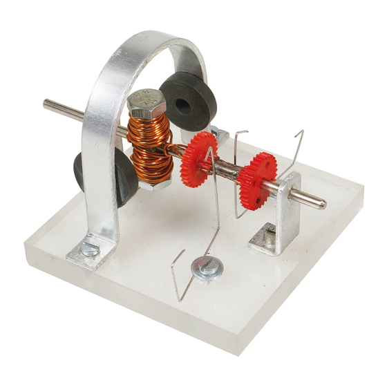
E l e c t r o m o t o r
Please Note
The OPITEC range of projects is not intended as play
toys for young children.They are teaching aids for
Warning!
young people learning the skills of Craft, Design and
This product contains small parts that can be swallowed.
Technolo- gy.These projects should only be undertak-
There is a danger of choking!
This product contains a magnet.
en and tested with the guidance of a fully qualified
Swallowed magnets can block the intestines and cause
adult. The finished projects are not suitable to give to
severe internal injury.
children under 3 years old. Some parts can be swal-
If a magnet is swallowed by accident contact a doctor as
lowed. Dan- ger of suffocation!
soon as possible.
1
D107388#1
Advertisement

Subscribe to Our Youtube Channel
Summary of Contents for Opitec 107.388
- Page 1 P r e m i u m - L i n e E l e c t r o m o t o r Please Note The OPITEC range of projects is not intended as play toys for young children.They are teaching aids for Warning! young people learning the skills of Craft, Design and This product contains small parts that can be swallowed.
- Page 2 D107388#1...
- Page 3 1. Product information: Art: Functioning model using metal & plastic Use: In Design Technology , Key stage 4 2. Materials: 2.1 Material: Aluminium ( Light, non ferrous metal ) Working: cutting ,filing, drilling Joining: machine screws. Finish: polish ,varnish. 2.2 Material: Acrylic plastic PMMA ( Polymethylmethacrylate ) transparent Working:...
- Page 4 4. Parts list : No. Quantity Description Material Size (in mm) Base Acrylic 8 x 70 x 70 Holder Aluminium strip 2 x 10 x 250 Holed strip metal 0,5 or 0,8 x 10 x 150 Shaft Metal axle Ø 3 x 95 Iron core Machine screw &nut M6 x 25...
- Page 5 6. Making the base 6.1 Making the holder and bearings 6.2 Making the core and commutator 6.3 Final assembly and testing 6.4 Principles of the electric motor General: In the pack are different materials for making the holder and bearings This choice depends on the difficulty of which level of model you make.
- Page 6 6.2 Making the holder and bearings At this stage you can chose your material Version 1 Using the holed metal strip, this is easy to bend into the U shaped holder. No need to drill holes.. Version 2 A more testing way is to make the U shaped holder from the aluminium strip This version has more stages of construction which must be accurately carried out.
- Page 7 6.3Making the core, coil and commutato 6.3.1 Drill two holes in one of the double gears (6) these holes should be between two teeth on the small gear and 1mm in diameter. Drill one side first and then the other on the opposite side. Ø...
-
Page 8: Final Assembly And Testing
6.3.5 Bend the two spring (7) contacts as shown. 30,0 6.4 Final assembly and testing: 6.4.1 Machine screw (9) and bolt ( nuts 10) the magnets to the U shaped holder or glue them in place. Note ! Check the polarity of the magnets !! Fix the magnets to the holder type as shown 6.4.2 Screw the bearing strips to the base as shown using two machine screws (11) Ensure that the hold the shaft and that it can turn easily. - Page 9 Principles of the electric motor How does an electric motor function Look at the diagram below Note: The same magnetic poles push against each other. Unlike attract each other. As the two permanent magnets here are always attracting each other –they can be switched on & off with an electro magnet.
- Page 10 D107388#1 D107388#1...
- Page 11 70,0 Patterns Scale 1:1 35,0 15,0 Base 145,0 Looped 28,0 holder No need to drill if the magnets are 10,0 glued in position ! Ø 3,0 147,0 Looped holder 10,0 35,0 Bearings 28,0 37,0 10,0 10,0 R 5,0 Ø 3,0 D107388#1 D107388#1...
- Page 12 D107388#1 D107388#1...
- Page 13 Patterns Ø 1,0 gear commutator 95,0 40,0 40,0 20,0 Drilled gear 30,0 D107388#1...
Need help?
Do you have a question about the 107.388 and is the answer not in the manual?
Questions and answers