
Related Manuals for Chromalox MWS Series

Summary of Contents for Chromalox MWS Series
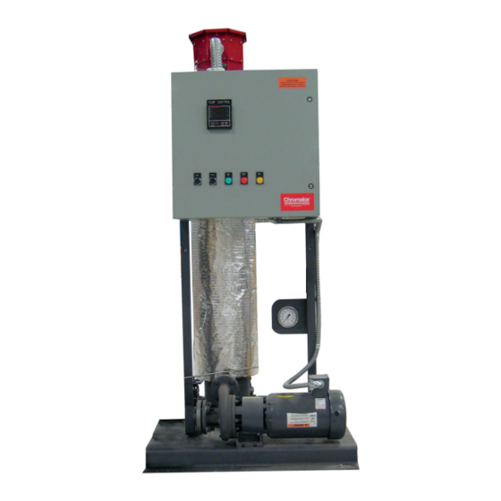
- Page 1 Installation & Operation Manual MWS Series Water & Water/Glycol System PQ449-2 161-123417-033 June 2019...
-
Page 2: Installation Instructions
The MWS series can operate up to 300˚F (149˚C) (de- ent. Consult Article 500 of the National Elec- pending upon heat transfer fluid properties and unit... -
Page 3: Fluid Compatibility
Fluid Compatibility other combustible atmospheres are present as defined in the National Electrical Code. Failure to comply can result in personal injury or prop- This system is NOT for use with oil based or erty damage. synthetic heat transfer fluids. DO NOT mix heat transfer fluids unless authorized and approved by the fluid manufacturer. -
Page 4: Relief Valve Installation
DO provide sufficient cross sectional area in the pro- DO NOT use Magnesium bed or porous insulations cess piping connections equivalent to the system which can absorb fluid. When soaked, these insula- pipes. In order to prevent undue pressure drop, maxi- tions will decrease unit efficiency and may cause a mum velocity in all piping should be less than 10 feet safety hazard for personnel. -
Page 5: Pump Motor
Expansion Tank Installation surized. This eliminates the possibility of heat transfer fluid flashing into vapor in the heater, at the point of Mount the expansion tank so it is the highest point in high velocity in the system, at the suction of the pump the system and if possible at least 15 feet (5m) above or causing the pump to vapor lock due to insufficient the height of the pump. - Page 6 175 - 250 kW Unit (5 hp) 1.0 S.G. TOTAL HEAD 60 Hz 3500 RPM 70°F MTRS FEET 5.38 U.S. GALLONS PER MINUTE CUBIC METERS PER HOUR 300 - 600 kW Unit (10 hp) 1.0 S.G. TOTAL HEAD 60 Hz 3500 RPM 70°F MTRS...
-
Page 7: Electrical Wiring
300 - 600 kW Unit (15 hp optional) Electrical Wiring ELECTRIC SHOCK HAZARD. Disconnect all power before installing or servicing heater. ELECTRIC SHOCK HAZARD. Any installation Failure to do so could result in personal injury involving electric heaters must be performed or property damage. -
Page 8: Filling System
Filling System 6. Turn master circuit breaker off. Bleed air from all lines (including one located above pump) and re- close all bleed valves. 7. The temperature limiting device located inside the To avoid possible damage to the heaters, DO control panel should be checked to insure man- NOT energize the heater until the system is ual reset buttons are in the closed position. -
Page 9: Operation
For complete process controller instructions, please refer to Chromalox manual PK510. Chromalox MWS unit is a component to a cus- If needed, factory settings for process controller can be tomer integrated process. Ensure adequate referenced per table below: safety devices have been installed and func- tion properly. -
Page 10: Maintenance
Figure 2 Optional Piping Accessory Assembly Start-Up Supervision Factory trained personnel are highly recommended for those customers who are unfamiliar with the initial Contact your local Chromalox sales office or call the start-up. Chromalox Service Center: 1-800-443-2640. Maintenance Contact your local Chromalox sales office or call the Factory trained personnel are recommended for those Chromalox Service Center: 1-800-443-2640. - Page 11 STANDARD HEAT TRANSFER SYSTEM TROUBLE SHOOTING CHART Problem Cause Corrective Action Main power feed off Turn on main power Circuit breaker off Turn on circuit breaker Control transformer Power light off Primary fuse blown Replace fuse Secondary fuse blown Replace fuse Transformer bad Check and/or replace Pilot light blown...
-
Page 12: Spare Parts
Relief Valve For Replacement Heater Bundle or spare parts not listed here, please contact Chromalox Service Center 1-800-443-2640 Limited Warranty: Please refer to the Chromalox limited warranty applicable to this product at http://www.chromalox.com/customer-service/policies/termsofsale.aspx. Chromalox, Inc. 2150 N. Rulon White Blvd.
Need help?
Do you have a question about the MWS Series and is the answer not in the manual?
Questions and answers