Table of Contents
Advertisement
Advertisement
Table of Contents

Summary of Contents for CTB BKSC GNX Series
- Page 1 CTB TECHNOLOGY Distributor CTB Co.,Ltd ADD: #9 Yunxi 6 Ave Development Zone Miyun Dist Beijing China Tel: +86 10-69076533 Fax: +86 10-69076577 24 Hours Free Hotline: 400-888-9055 DATA NO.: ZL-18-1118-IBCN The information may be changed while the product is being improved without further notice.
- Page 2 GH DRIVER Operating manual AC servo driver Model: BKSC - □ □ □ □ GHX Class 400V, 1.5 ~ 315KW (2.5 ~ 460KVA) Please send the manual to final user, and keep it properly. CTB Co., Ltd. DATA NO.: ZL-18-1118-IBCN...
- Page 3 GH DRIVER Preface Thank you for purchasing GH series servo driver produced by Beijing CTB Servo Co., Ltd. The GH series AC servo driver is a high-quality, multi-functional and low-noise AC servo driver that was researched, developed and manufactured by Beijing CTB Servo Co., Ltd. The driver is servo driver for AC induction motor (IM) and AC permanent magnet synchronous motor (PM).
-
Page 4: Safety -Related Symbol Description
GH DRIVER Safety -related symbol description The following symbols are used for safety-related content in the manual. Sentences marked by the safety symbols describe important content, and must be abided. If the requirements in the safety-related content are not abided, application of the product may lead to abnormal product operation, damage to the product, even danger and personal injury. -
Page 5: Safety Precautions
GH DRIVER Safety precautions Unpacking inspection ◆ For risk of injury, please do not install damaged or part missing driver. ● Caution Installation ◆ For risk of fire, please install the equipment on nonflammable metal plate without ● combustible materials around. Please be sure to tighten the mounting screws of the driver. - Page 6 GH DRIVER Wiring ◆ For risk of injury and fire, please ensure that the voltage of the main circuit AC input ● power and the rated voltage of the driver are consistent. Please do not conduct withstand voltage and insulation test to the controller arbitrarily. ●...
- Page 7 GH DRIVER Maintenance and inspection ◆ For risk of electric shock, please do not directly touch terminals of the controller. Some ● of them have high voltage and very dangerous. For risk of electric shock, please do install the housing before power-on; and must ●...
-
Page 8: Table Of Contents
GH DRIVER Table of contents Preface ...................................... 1 Safety -related symbol description ..........................2 Safety precautions ................................3 Chapter 1 - Installation ..................…………………………………………..…………………………. 1-1 Introduction to GH DRIVER ................…..………………………….…..……………………… 1-2 Unpacking inspection .....................……………………………………..………..… 1-3 Standard specifications and performance parameters ..................1-4 Driver nameplate description ……………………………..............………………………..…………... - Page 9 GH DRIVER Chapter 5 - Parameter list …………………………………………………..................………………… 5-1 Running monitoring parameter U1 ………………………………………............……….………………. 5-2 Running monitoring parameterU2 ……………………………………………………............…………. 5-2 Malfunction state record parameter U3 ………………………………..........……………….…………… 5-4 Basic parameter A1 …………………………………………………….…................….………….. 5-5 User self-defined parameter A2 ……………………………………………............……………..………… 5-7 User self-defined parameter A3 ………………………………….………………............…….….……… 5-10 Bn bus parameters group ………………………………….………………………….............…………..
- Page 10 GH DRIVER Installation The chapter describes matters to be confirmed and installation requirements for the user after getting the GH DRIVER. Introduction to GH DRIVER ..............…… 1-2 Unpacking inspection ................… 1-3 Standard specifications and performance parameters ....1-4 Driver nameplate description ……………………………......… 1-5 External dimensions and installation dimensions ………….…………...
-
Page 11: Introduction To Gh Driver
CNC milling machine, CNC drilling machine, CNC lathe, CNC grinder, and feed motor of large gantry equipment and vertical lathe. To achieve the best operation effect, please complete wiring with CNC system by the “CTB servo application manual “, and carry out installation and commissioning in accordance to the manual. -
Page 12: Unpacking Inspection
GH DRIVER Code Item Description Illustrated model meaning None: standard products E: Ethercat bus M: Mecholink bus J: electro-hydraulic servo C: CANopen bus Special label Ethercat bus PN: Profinet bus PB: Profobus PL: powerlink bus M2: Mecholink Ⅱ bus M3: Mecholink Ⅲ bus None: standard products Battery options Equipped with batteries... -
Page 13: Standard Specifications And Performance Parameters
GH DRIVER Standard specifications and performance parameters Please see Table 1-4 for standard specifications and performance parameters of 3-phase Class 400V driver Table 1-4 Standard specifications and performance parameters of GH DRIVER Model BKSC-XXXXGHX 41P5 42P2 43P4 45P5 47P5 4011 4015 4018 4022 4030 4037 4045 4055 4075 4090 4110 4132 4160 4200 4250 4315 Adapt motor power KW 1.5 2.2 3.7 5.5 7.5 11 15 18.5 22 90 110 132 160 200 250 315... -
Page 14: Driver Nameplate Description
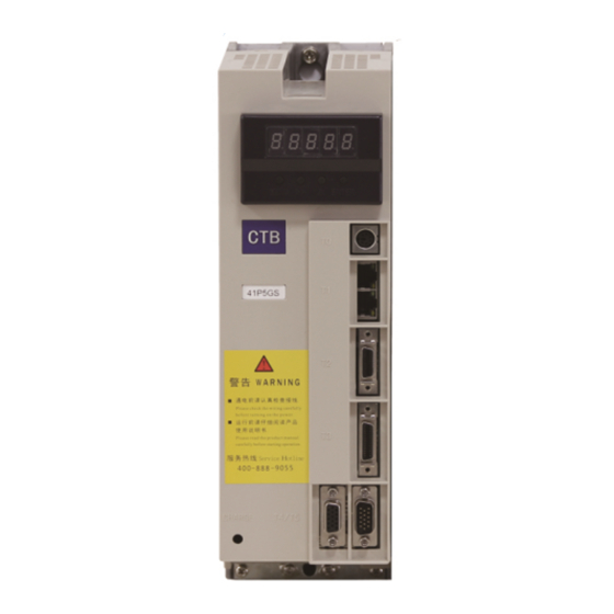
Figure 1-1 AC Servo driver nameplate Note: the two-dimension code includes manufacturing number of the driver; customer name of the driver (take BEIJING CTB SERVO CO., LTD. as an example); contract number; driver model; main board model; software number; non-standard (take standard as an example) and other description. - Page 15 GH DRIVER 2、5.5 ~ 11kw driver Please see diagram 1-3 for external dimensions and installation dimensions Figure 1-3 Table 1-6 Dimensions (mm) and weight (kg) of GH DRIVER (5.5-11kw) driver Dimension Connecting terminal screw Installation screw Weight (kg) Model BKSC-45P5GHX Wire nail width BKSC-47P5GHX BKSC-4011GHX...
- Page 16 GH DRIVER 4 、 55 ~ 160kw driver Please see diagram 1-5 for external dimensions and installation dimensions Figure 1-5 Table 1-8 Dimensions (mm) and weight (kg) of GH DRIVER (55-160kw) driver Connecting terminal Dimension Installation screw Weight (kg) Model screw BKSC-4055GHX BKSC-4075GHX...
-
Page 17: Confirmation And Requirements Of The Installation Space
GH DRIVER Confirmation and requirements of the installation space Installation environment The following items shall be noted when selecting the installation environment: 1. Ambient temperature: operate in -10 ℃ ~ 45 ℃ ; if the ambient temperature is higher than 45 ℃ , the equipment shall be used with 30% derating for each 5 ℃... -
Page 18: Notes On The Driver
GH DRIVER High-speed operation in constant power area For high-speed operation in constant power area, the increased vibration and noise shall be considered, and the service speed range of motor bearing and mechanical devices must be confirmed, and consulted in advance. It’s strictly prohibited to make the machine operate above the rated speed. -
Page 19: Notes On Scrapping
GH DRIVER Lightning attack protection lightning over-current device is equipped in the driver for self-protection to induction stroke Altitude and derating operation For areas with altitude over 1000 m, derating operation is necessary due to deterioration of cooling effect of the drive caused by thin air. - Page 20 GH DRIVER Wiring The chapter describes the wiring specifications of power supply terminals and control circuit terminals, and install wiring specifications of control board jumpers and expansion interface board. Selection and connection of peripheral devices ……………….……… 2-2 Wiring of the main circuit terminals ………………………………………...…… 2-3 Control circuit wiring ……………..…………………………………....…...
-
Page 21: Selection And Connection Of Peripheral Devices
GH DRIVER Selection and connection of peripheral devices Driver and peripheral devices connection diagram taking 7.5kw drives as an example in Figure 2-1. Power supply pcpc 3-phase 380V ~ 440V Monitoring computer Air circuit breaker Electromagnetic contactor Bus interface CNC system Pulse signal Input side reactor I/O signal... -
Page 22: Wiring Of The Main Circuit Terminals
GH DRIVER Wiring of the main circuit terminals The structure of the main circuit See Figure 2-2A, 2-2B, 2-2C and 2-2D for internal structure diagram of the main circuit. Figure 2-2A 1.5~11kw main circuit composition Figure 2-2B 15~30kw main circuit composition P1 P2 Figure 2-2C 37~75kw main circuit composition Figure 2-2D 90~160kw main circuit composition... - Page 23 GH DRIVER 90~160kw main circuit terminals composition Main circuit terminals and functional description Item Function Notes R S T 3-phase AC supply input terminal. 380~440V, 50/60Hz Need to install breaker for protection P and N are for input of external braking unit or DC P P1 DC bus positive pole power input...
- Page 24 GH DRIVER Caution Installation of the residual current circuit breaker The output of the servo driver is a high frequency PULSE wave so that there is high-frequency leakage current generated. Residual current circuit breaker can be used at the incoming line side of the driver to remove high-frequency leakage current, and only inspect channel current that dangerous to human body.
- Page 25 GH DRIVER Table 2-1 Selection of AC reactor, DC reactor and input filter Driver model 41P5 42P2 43P7 45P5 47P5 4011 4015 4018 4022 4030 4037 4045 4055 4075 4090 4110 4132 4160 CURRENT reactor 0005 0007 0010 0015 0020 0030 0040 0050 0060 0080 0090 0120 0150 0200 0230 0250 0290 0350 MODEL ACL CURRENT Without connection to DC reactor...
- Page 26 GH DRIVER The wiring of output side of main circuit The output terminals U, V and W of the driver should be connected to the terminals U, V and W of three-phase AC motor in the correct phase sequence. If the phase sequence is wrong, the driver will send out an error alarm E.SE or E.OL2. At this time, it is necessary to change the phase sequence of any two phases.
- Page 27 GH DRIVER Filter magnetic ring Installing filter magnetic ring at the output side near to the driver can suppress common code interference at the output side effectively, as shown in Figure 2-9. MCCB Power supply It’s prohibited to make Servo the earth wire passing the filter magnetic ring Over 30cm away...
- Page 28 Over 30cm away GH DRIVER Signal line Control equipment Connection of the grounding wire The ground terminal is identified as E or , please do ground. ● Earth resistance: below 4 Ω . ● Do not share grounding wire with welder and other power equipment. ●...
- Page 29 GH DRIVER Selection of breaker, contactor and cable Please see Table 2-3 for selection of breaker, contactor and input and output cable Table 2-3 Specif ication of breaker, contactor and cable 断路器 Main circuit cable Contactor Model Power Breaker (空气开关) (copper conductor cable) Voltage: 380V.
-
Page 30: Control Circuit Wiring
GH DRIVER Control circuit wiring Input and output signals of GH Series AC servo driver include: switching value input signal, switching value output signal, Analog input signal, PULSE input signal, encoder input / output signal. Specifications of input and output signal cable As the control signals are different, the requirements to cable for connector are strict. - Page 31 GH DRIVER Standard version control wiring diagram (taking 7.5kW GH X driver as an example) PS/2 RS232 communication interface Speed setting power DC10V/50mA Analog output 1 DA1/-10~10V Analog input 1 -10~10V Analog input 2 0~10V/4~20mA Analog output 2 DA2/-10~10V Analog common terminal Shielded cable connection terminal Driver ready Speed reached...
- Page 32 GH DRIVER Input and output signals description (GHX Series) Table 2-6 Input and output signal function description Port Type Name Function Signal standard Communication communicate with computer RS232 10V power for speed setting is provided inside DC10V 50mA common port analog input /output common terminal Analog input -10V~+10V analog input, input impedance: 20K Ω...
- Page 33 GH DRIVER General version control wiring diagram (taking 7.5kW GHXB driver as an example) PS/2 RS232 communication interface Control power supply(DC24V) PV Control signal commom terminal NPN/PNP selection RJ45 High-speed bus interface Servo enabling Reset Running reset Reverse Speed setting power Orientation DC10V/50mA Analog input 1...
- Page 34 GH DRIVER Input and output signals description (GHXB Series) Table 2-7 Input and output signal function description Port Type Name Function Signal standard Communication Communicate with computer RS232 High-speed bus MechatroLink, PowerLink, Ethercat Bus communication Standard Ethernet interface 10V power for speed setting is provided inside common port DC10V 50mA Analog input /output common terminal Analog input...
- Page 35 GH DRIVER Connector terminal arrangement 15 14 13 12 11 T2 20-pin high density plug T330-pin high density plug T4 D-type 15-pin plug (pin) T5 D-type 15-pin plug (hole) Definition of motor side encoder interface Definition ofrectangular connector 9 10 Table2-9 Definition of rectangular connector interface Pin number Signal (color)
- Page 36 GH DRIVER Table 2-10Definition of round ST1210/S9connector interface Pin number Signal (color) Encoder type Absolute encoder (blue (brown (blue) (brown) (purple) (shielded) (black) (red) black) black) Smart card Round YD18K15TS/YD28K15TS Table 2-11 Definition of round YD18K15TS/YD28K15TSconnector interface Pin number Signal (color) Encoder type Sine and cosine encoder (white...
- Page 37 GH DRIVER 圆形WY20J12TE 表2-12 圆形WY20J12TE连接器接口定义 Pin number Signal (color) Encoder type Sine and cosine (brown (green (grey (blue (red (black (brown) (green) (grey) (blue) (red) (black) encoder white) white) white) white) white) white) Incremental encoder (brown (green (grey (blue (red (black (brown) (green)
- Page 38 GH DRIVER Wiring of analog input signal GH AC servo driver selects two analog input interfaces of FI and FV, as well as a group of power interface FS and FC for analog input. Please see Table 2-13 for signal function description. Table 2-13 Analog interface signal description Signal Function...
-
Page 39: Connection Of The Encoder Interface
GH DRIVER Forbid ● It’s prohibited to connect the signal line and OV reversely. The signal line is likely to be burned, and reverse operation may be caused for bipolar. ● It’s prohibited to connect high-voltage to analog signal terminal. The driver may be burned. Connection of the encoder interface A group of encoder input interface T5 and encoder input interface T4 are provided on main board of GH series AC servo driver. -
Page 40: Connection Of Serial Communication Port
GH DRIVER Encoder wiring precautions ● The encoder cable must be shielded twisted pair cable. ● The shielding layer shall be connected to the connector housing Forbid It’s prohibited to connect the DC5V power reversely. It’s likely to burn the DC5V power or ●... - Page 41 GH DRIVER Manipulator application The chapter describes the functions and methods of application of the manipulator. Digital tube display 0.4 ~ 18.5kw driver: Configuration and key functions of the manipulator ……………… 3-2 The operating state of the driver …………………………………………………… 3-3 Operative mode of the manipulator …………………………………………...…...
- Page 42 GH DRIVER Configuration and key functions of the 0.4 ~ 18.5kw driver digital tube manipulator The chapter defines and describes terms and phrases for operation and state of 0.4 ~ 18.5kw driver manipulator, defines the operation methods of driver and manipulator. Please read carefully. It’s very helpful for proper use of the 0.4 ~ 18.5kw driver. Manipulator The manipulator is one of the standard equipment of 1.0~ 18.5kw driver.
-
Page 43: The Operating State Of The Driver
GH DRIVER Manipulator key function description Please see Table 3-1 for function description of the manipulator key Table 3-1 Manipulator key function Name Function MENU Menu selection switching key switching key of each menu item; It’s used to switch data bit of the parameter number when browse parameter items; Shift key When modifying data in program state, it can be used to modify the modified bit of the modified data. -
Page 44: Operative Mode Of The Manipulator
GH DRIVER Operative mode of the manipulator Standby state The state of the manipulator is shown in Figure 3-2 when the driver is in standby state. The LED digital tube default display F . 0 . At this point, user may press to enter menu items, and check or modify parameters. -
Page 45: Modify The Parameters With The Manipulator
GH DRIVER Modify the parameters with the manipulator The flow chart of modify the parameters with the manipulator is shown in Figure 3-6. MENU MENU MENU Start F . 0 1-Level menu MENU MENU (parameter group) MENU MENU MENU MENU ENTER 2-Level menu Fn.00... - Page 46 GH DRIVER Fault information monitoring The control panel will display the current fault message code when the driver is in fault state. The fault record of the driver can be checked through U3. The check operation is same with monitoring parameter, only needs to select corresponding parameter in U3. Please see fault state recording parameter table U3 for parameter number.
- Page 47 GH DRIVER Manipulator key function description Please see Table 3-2 for function description of the manipulator key Table 3-2 Manipulator key function Name Function MENU Menu select and switch key switching key of each menu item Press the key in program state to return to the previous menu; Enter the next level menu;...
-
Page 48: The Operating State Of The Driver
GH DRIVER The operating state of the driver 22~315kw driver has four operating states after power-on: standby, operating, setting, modifying or editing and fault alarm. They are described as follows: Standby state 22~315kw driver is in standby state after power-on and before receiving any operating control order. The Run state indicator (RUN) on operation panel is off, and the default tandby state display function code of LED digital tube is F . -
Page 49: Use Method Of The Manipulator
GH DRIVER Operating state The driver enters operating state after receiving correct operation command in standby state. As shown in Figure 3-10, the LED digital tube default displays the set speed of the driver, e.g F. 500 . In this state, user may press MENU to enter menu items, and check or modify parameters. -
Page 50: Monitor Operating State With The Manipulator
GH DRIVER Description: ★ 10 menu items are included in 1-level menu: U1menu, U2 menu, U3 menu, A1 menu, A2 menu, A3 menu, Bn menu 、 Cn menu 、 Dn menu 、 En menu 、 Fn menu 、 Hn menu 、 Pn menu 、 Sn menu Please see parameter description for detailed function in 2-level menu. - Page 51 GH DRIVER Test run The chapter describes methods and precautions for initial test run of the driver Basic procedure of test run ……………………………..…………....… 4-2 Confirmation of connection of the main circuit ……………………...… 4-2 Motor and driver parameters confirmation ……………………………...… 4-3 Loaded test run ……………………………………………………......……...
-
Page 52: Basic Procedure Of Test Run
GH DRIVER Basic procedure of test run The initial power-on operation of the driver shall be carried out by the following procedures, otherwise, accident, damage to equipment or other hazards are likely to happen. 1.Confirm that the mounting screws of the driver are tightened. -
Page 53: Motor And Driver Parameters Confirmation
GH DRIVER 3. When the output terminal of the driver is connected to the motor, it shall beensured that their phase sequences are same, otherwise, he motor cannot operate normally, and prone to burn the equipment. If shield cable is used for output cable, the shielding layer at the ends of the cable shall be connected respectively to ground terminal of the drive and motor. -
Page 54: Chapter 5 - Parameter List
GH DRIVER Parameter list The chapter describes all of parameters of the driver. Running monitoring parameter U1 ………………………………………..…. 5-2 Running monitoring parameterU2 ……………………………………………….. 5-2 Malfunction state record parameter U3 ………………………………..… 5-4 Basic parameter A1 …………………………………………………….…...... 5-5 User self-defined parameter A2 ……………………………………………..… 5-7 User self-defined parameter A3 ………………………………….……………..…... -
Page 55: Running Monitoring Parameter U1
GH DRIVER Parameter list description The contents of the parameter list are described as follows: Function code: Code of parameter group and parameter number; Name: Name of the parameter; Description: Detailed description about function and effective setting value of the parameter; Setting range: The range of effective setting value of parameter;... - Page 56 GH DRIVER Function Apply Name Description Unit Change code motor Analog quantity -10 to 0 to +10V Synchronous/ U2.06 Analog quantity input FVdigital * Asynchronous Digital 0 to 2047 to 4095 Analog quantity 0 to +10V Synchronous/ U2.07 Analog quantity input FIdigital *...
-
Page 57: Malfunction State Record Parameter U3
GH DRIVER Function Apply Name Description Unit Change code motor bit 0: zero torque status bit 1: magnetic pole position study completed bit 2: Motor self-tuning completed bit 3:brake output bit 4: Arrival software positive limit bit 5: Arrival software opposite limit bit 6: Arrival hardware positive limit bit 7:Arrival hardware opposite limit Synchronous/... -
Page 58: Basic Parameter A1
GH DRIVER Function Apply Name Description Unit Change code motor Synchronous/ U3.10 One time fault time Drive power on time when one time fault occurs * Asynchronous Synchronous/ U3.11 two times fault time Drive power on time when two times fault occurs *... - Page 59 GH DRIVER Function Setting Factory Recommend Name Description Unit Change code scope setting motor A1.06 Save ~ A1.10 400: Parameter backup set Synchronous/ A1.11 Parameter backup 0~6553.5 Asynchronous 401: Clear backup parameters parameter Synchronous/ A1.12 9055: Parameter recovery 0~6553.5 △ Asynchronous recovery A1.13...
-
Page 60: User Self-Defined Parameter A2
GH DRIVER Function Setting Factory Recommend Name Description Unit Change code scope setting motor IPM motor Iq IPM motor index table corresponds to max Synchronous/ A1.97 0~6553.5 × Asynchronous index 8 torque * 8/10 q-axis current IPM motor Iq IPM motor index table corresponds to max Synchronous/ A1.98 0~6553.5... - Page 61 GH DRIVER Function Setting Factory Recommend Name Description Unit Change code scope setting motor 0: accurate stop as per current speed direction Accurate stop Synchronous/ A2.13 1: accurate stop as per the direction of A2.14 × Asynchronous mode selection setting Accurate stop 0: positive accurate stop Synchronous/...
- Page 62 GH DRIVER Function Setting Factory Recommend Name Description Unit Change code scope setting motor A2.28 Save A2.29 0: invalid 1: Torque control I5 function 2: Low speed function Synchronous/ A2.30 × Asynchronous selection 3: Zero speed lock shaft 4: outer fault input(normal close) 5: approach switch positioning I5 torque control 0: FV potentiometer...
-
Page 63: User Self-Defined Parameter A3
GH DRIVER User self-defined parameter A3 Function Setting Factory Recommend Name Description Unit Change code scope setting motor Motor encoder 0: positive count Synchronous/ A3.00 0, 1 × Asynchronous direction 1: reverse count Motor running 0: CCW is positive running Synchronous/ A3.01 0, 1... - Page 64 GH DRIVER Function Setting Factory Recommend Name Description Unit Change code scope setting motor Set the speed threshold when the second set of PI parameters take effect.When the output Speed ring second ○ speed is less than the set speed value, the Synchronous/ A3.13 set of parameters...
- Page 65 GH DRIVER Function Setting Factory Recommend Name Description Unit Change code scope setting motor Set speed loop integral time Ti at analog/ ○ speed loop integral Synchronous/ A3.34 pulserigid tapping. The rigidity is higher with 0~65535 Asynchronous time at Rigid tapping lower value Set position loop scale gain at pulserigid tapping.
- Page 66 GH DRIVER Function Setting Factory Recommend Name Description Unit Change code scope setting motor ○ Swing reverse Synchronous/ A3.53 Set swing reverse direction range 0~36000 6000 Asynchronous direction range ○ Swing acceleration 0.01s/ Synchronous/ A3.54 Set swing speed loop acceleration time 0~30000 Asynchronous speed...
-
Page 67: Bn Bus Parameters Group
GH DRIVER Bn bus parameters group Function Setting Factory Recommend Name Description Unit Change code scope setting motor Synchronous/ Bn.00 Modbus station Modbus slave station No setup 1~254 △ Asynchronous 0: 9600 Modbus 1: 19200 Synchronous/ Bn.01 communication 2: 38400 △... - Page 68 CAN slave station enable selection setting Asynchronous enable selection ○ CAN Execution Synchronous/ Bn.33 CAN Execution cycle setting 0~20 Asynchronous cycle setting 0: CTB 1: CANOPEN ○ Synchronous/ Bn.34 CAN model 2: The Big Dipper Asynchronous 3: EV car 4: Upper computer ○...
- Page 69 GH DRIVER Function Setting Factory Recommend Name Description Unit Change code scope setting motor 0 , 1 ○ Bus off enable 0: free stop Synchronous/ Bn.38 Asynchronous mode 1: Trigger emergency stop, power down storage Bit0: Servo encabling Bus bit control Bn.39 Bit1: Servo reset lower 16 bits...
- Page 70 GH DRIVER Function Setting Factory Recommend Name Description Unit Change code scope setting motor Current speed Bn.61 lower 16 bits Current feedback speed is calculatedby bus _2147483647 Synchronous/ Asynchronous gear ratio _2147483647 Current speed Bn.62 higher 16 bits Actual motor position, determined by the Bn.63 Motor position L Synchronous/...
-
Page 71: User Parameters Cn
GH DRIVER User parameters Cn Function Setting Factory Recommend Name Description Unit Change code scope setting motor Motor running 0: anticlockwise is forwardrunning Synchronous/ Cn.00 Asynchronous direction 1: clockwise is forward running ○ Synchronous/ Cn.01 acceleration time speed modeacceleration time 0~200.00 Asynchronous ○... - Page 72 GH DRIVER Function Setting Factory Recommend Name Description Unit Change code scope setting motor Speed loop proportional gain Kp setting, ○ Motor 1 speed loop Synchronous/ effective when the output speed is lower than Cn.21 0~65535 Asynchronous 2nd proportional gain the set value of cn.23 Motor 1 speed ring The speed integral time constant Ti is set, and...
- Page 73 GH DRIVER Function Setting Factory Recommend Name Description Unit Change code scope setting motor 0: speed loop 2nd proportional gain, integral time constant Motor 2 speed loop PI ○ invalid Synchronous/ parameter switching Cn.43 0~6000.0 Asynchronous When the set value is not equal to 0, and the speed output speed is less than the set value, Cn.41 and Cn.42 will take effect...
- Page 74 GH DRIVER Function Setting Factory Recommend Name Description Unit Change code scope setting motor In the case of open loop vector control, speed ○ Estimated coefficient Synchronous/ of stator resistance on-line estimation, 0 means Cn.61 0~200 Asynchronous of stator resistance no on-line estimation of resistance Open loop vector control, Turning angle Turning angle...
-
Page 75: Motor Driving Parameter Dn
GH DRIVER Function Setting Factory Recommend Name Description Unit Change code scope setting motor Cn.82 ~ Save Cn.89 Maximum output Synchronous/ Cn.90 Output maximum voltage ratio setting 60~120 Asynchronous voltage ratio Voltage closed loop Synchronous/ Cn.91 Voltage closed loop KP setting 30~2000 Asynchronous Voltage closed loop... - Page 76 GH DRIVER Function Setting Factory Recommend Name Description Unit Change code scope setting motor First motor rated Synchronous/ First motor rated frequency Dn.06 0~6000.0 50.8 Asynchronous frequency Synchronous/ First motor rated torque First motor rated torque Dn.07 0~60000 Asynchronous Synchronous/ number of pole-pairs number of pole-pairs Dn.08 0~10000...
- Page 77 GH DRIVER Function Setting Factory Recommend Name Description Unit Change code scope setting motor Synchronous/ motor rated speed 2 motor rated speed Dn.26 0~60000 1500 × Asynchronous Synchronous/ motor rated voltage 2 motor rated voltage Dn.27 0~20000 × Asynchronous Synchronous/ Dn.28 motor rated power 2 motor rated power...
- Page 78 GH DRIVER Function Setting Factory Recommend Name Description Unit Change code scope setting motor 2nd motor slip compensation 2nd motor slip compensation coefficient Dn.46 0~1000 × Asynchronous coefficient 2nd motor peak Synchronous/ Motor theoretical peak torque Dn.47 0~65535 × Asynchronous torque Dn.48 Save...
-
Page 79: Encoder Parameter En
Factory Recommend Name Description Unit Change code scope setting motor 0: CTB encoder 1: TTL 2: TTL_UVW 3: Resolver 4: Sin-cosine encoder 10: Tamagawa 8401 encoder 11: Tamagawa 8401 encoder 8501 encoder 12: Tamagawa N8 Motor encoder type Synchronous/ 13: Tamagawa N9 En.00... - Page 80 GH DRIVER Function Setting Factory Recommend Name Description Unit Change code scope setting motor Manual self- 0: invalid learning instruction 1. Learning method of magnetic pole location En.12 Synchronous for magnetic pole 2: static learning trigger of magnetic pole position (T5) position Self-learning value of magnetic pole...
- Page 81 GH DRIVER Function Setting Factory Recommend Name Description Unit Change code scope setting motor Encoder Z phase Synchronous/ Encoder Z phase counting value monitoring En.27 0~65535 Asynchronous counting value (T5) Absolute encoder Absolute encoder multi-turn count value Synchronous/ multi-turn count monitoring, suitable for TAMAGAWA absolute En.28 0~65535...
- Page 82 GH DRIVER Function Setting Factory Recommend Name Description Unit Change code scope setting motor Sine-cosine Synchronous/ encoder B phase En.52< 0.5V or En.52> 1.5V encoder abnormal En.52 0~3.3 Asynchronous amplitude value Sine-cosine Synchronous/ encoder ZA phase En.53< 0.5V or En.53> 1.5V encoder abnormal En.53 0~3.3 Asynchronous...
-
Page 83: Fn Function Parameters
GH DRIVER Fn function parameters Function Setting Factory Recommend Name Description Unit Change code scope setting motor 0: absolute position 1: incremental location 2: relative Z phase positioning ○ Positioning mode 3: position synchronization Synchronous/ Fn.00 Asynchronous selection 4: real-time positioning 5: single turn absolute positioning 6: external IO quasi-stop 7: swing positioning... - Page 84 GH DRIVER Function Setting Factory Recommend Name Description Unit Change code scope setting motor ○ swing acceleration Synchronous/ Acceleration time during swing Fn.18 0~300.00 s/krpm Asynchronous time ○ swing deceleration Synchronous/ Deceleration time during swing Fn.19 0~300.00 s/krpm Asynchronous time ○...
- Page 85 GH DRIVER Function Setting Factory Recommend Name Description Unit Change code scope setting motor ○ PID internal Internal feedback register operates as per a Synchronous/ Fn.32 0~100.0 Asynchronous feedback register percentage of the relative feedback PID given feedback range is dimensionless unit, ○...
- Page 86 GH DRIVER Function Setting Factory Recommend Name Description Unit Change code scope setting motor PID given PID to the quantitative acceleration and ○ Synchronous/ Fn.47 acceleration and deceleration time, can alleviate the impact 0~50.00 Asynchronous deceleration time caused by too fast change PID feedback low-pass filter, 0 means no ○...
- Page 87 GH DRIVER Function Setting Factory Recommend Name Description Unit Change code scope setting motor -500.0 Synchronous/ Fn.65 Torque output value Motor output torque, percentage of rated torque Asynchronous ~500.0 Fn.66 Save Fn.79 0: internal register 1: current torque instruction, output in proportion to the maximum torque DA1 output source 2: current torque feedback, output in proportion...
-
Page 88: Hn Interface Parameter Set
GH DRIVER Function Setting Factory Recommend Name Description Unit Change code scope setting motor ○ When the difference between feedback torque Zero torque reach Synchronous/ Fn. 96 0~500.0 Asynchronous range and zero torque is less than fn.96and duration time exceeds fn.97,output the state of zero ○... - Page 89 GH DRIVER Function Setting Factory Recommend Name Description Unit Change code scope setting motor ○ 0: PLC control Synchronous/ Hn. 13 RES reset terminal 0, 1 Asynchronous 1: reset input Filter time constant of multifunctional Input terminal filtering time ○ Synchronous/ Hn.
- Page 90 GH DRIVER Function Setting Factory Recommend Name Description Unit Change code scope setting motor 0 : Disable 1 : Effective bit0 : Enable bit1 : Reset bit2 : Positioning trigger bit3 : Emergency stop trigger bit4 : Retain bit5 : Zero speed lock shaft Drive internal bit6 : Star / Delta switch trigger ○...
- Page 91 GH DRIVER Function Setting Factory Recommend Name Description Unit Change code scope setting motor ○ Analog calibration 0: calibration function is on Synchronous/ Hn. 35 0, 1 Asynchronous function selection 1: calibration function is off Minimum allowable The minimum threshold is the maximum value ○...
- Page 92 GH DRIVER Function Setting Factory Recommend Name Description Unit Change code scope setting motor ○ T2 pulse count 0: increment count Synchronous/ Hn. 52 0, 1 Asynchronous direction 1: subtraction T2 pulse position Hn. 53 electron gear ratio numerator L ○...
- Page 93 GH DRIVER Function Setting Factory Recommend Name Description Unit Change code scope setting motor T3 pulse speed Hn. 69 electron gear ratio numerator L ○ T3 speed pulse electronic gear ratio numerator - 2147483647 Synchronous/ Asynchronous setting ~2147483647 T3 pulse speed Hn.
-
Page 94: Pn Protection Parameter Set
GH DRIVER Function Setting Factory Recommend Name Description Unit Change code scope setting motor T4 pulse speed Hn. 84 electronic gear ratio denominator L ○ T4 speed pulse electronic gear score master - 2147483647 Synchronous/ Asynchronous setting ~2147483647 T4 pulse speed Hn. - Page 95 GH DRIVER Function Setting Factory Recommend Name Description Unit Change code scope setting motor 0: temperature switch Temperature 1: Temperature resistance pt3c protection 2: Temperature resistance kty84 ○ Synchronous/ Pn. 10 Asynchronous selection 3: Temperature resistance Pt100 9: Shielding Thermistor / temperature switch channel selection: when multi-channel is selected, the temperature of U2 group motor is displayed according to the maximum temperature, and...
- Page 96 GH DRIVER Function Setting Factory Recommend Name Description Unit Change code scope setting motor When the PID feedback quantity is less than the PID feedback loss ○ Synchronous/ feedback loss detection value, and the duration Pn. 22 0~100.0 Asynchronous detection window is longer than the PID feedback loss detection time, the servo state PID feedback abnormal setting.
- Page 97 GH DRIVER Function Setting Factory Recommend Name Description Unit Change code scope setting motor External encoder 0: shielding, no detection and alarm 0 , 1 ○ Synchronous/ Pn.35 Asynchronous fault alarm shielding 1: Alarm e1.ec2 when encoder failure Pn.36 Save Pn.43 Line resistance 0: close...
-
Page 98: Sn System Parameter Set
GH DRIVER Sn system parameter set Function Setting Factory Recommend Name Description Unit Change code scope setting motor After entering the password, you can modify some parameters of Sn, Sn system Synchronous/ Sn.00 Senior password 0~65535 Asynchronous Parameters are important parameters of the drive and should be modified carefully Set the power code of the driver, modify it by Synchronous/... - Page 99 GH DRIVER Function Setting Factory Recommend Name Description Unit Change code scope setting motor -3000.00 Torque current Synchronous/ Sn.17 Torque current feedback * Asynchronous feedback ~3000.0 Magnetizing -3000.00 Synchronous/ Magnetizing current feedback Sn.18 * Asynchronous current feedback ~3000.0 0~ U phase current Synchronous/ Sn.19 U phase current sampling AD value...
- Page 100 GH DRIVER Set parameter by function The chapter helps user for parameter setting and debugging by function of use. Analog speed control ……………………………..........6-2 Pulse speed control …………………………………..........… 6-4 Analog rigid tapping …………………………………………….……………....… 6-5 Pulse rigid tapping /pulse position ………………….……………....… 6-6 Accurate stop ……………………………………………………........…...
-
Page 101: Analog Speed Control
GH DRIVER 6.1 Analog speed control 6.1.1 Terminal definition and function parameters position control parameter Analog value Port Signal Function needs to be modified ±10V analog voltage input A2.01=0 Analog voltage input common terminal ±10V analog voltage A2.15=0 Operation enabling (forward or reverse is determined by polarity of the analog voltage) 0~10V analog voltage input Analog voltage input common terminal... - Page 102 GH DRIVER 6.1.4 Analog calibration and relevant parameter Function Factory Item Description Unit code range setting Analog calibration function 0:Calibration function open Hn.35 selection 1:Calibration function close The minimum threshold value is the Analog calibration allowable maximum value of the analog×H1.36 %, and Hn.36 0~50 minimum threshold value...
-
Page 103: Pulse Speed Control
GH DRIVER 6.2 Pulse speed control 6.2.1 Terminal definition and function parameters Orthogonal pulse speed forward/reverse Relavent parameters Definition Port Signal Function need to modify Forward or/reverse rotation enabling (forward or Enabling Control A2.15=1 reverse is determined by direction of the pulse) Orthogonal Pulse phase A input A2.17=1 A2.16=15... -
Page 104: Analog Rigid Tapping
GH DRIVER 6.2.3 Pulse control sequence chart Please see the following table for single pulse control interface, and see the right diagram for control sequence. Control terminal Function PULSE+ PULSE PULSE- DIRET DIR+ Forward operation Operation state DIR- Reverse operation Pulse interface of CNC system and GH X series Single pulse input sequence chart Please see the following table for dual pulse control interface, and see the right diagram for control sequence. -
Page 105: Pulse Rigid Tapping /Pulse Position
GH DRIVER 6.3.2 Relevant parameters of analog rigid tapping Function Factory Item Description Unit Set range parameter setting A3.30 maximum speed during rigid tapping set maximum speed of motor during rigid tapping 0~60000 1500 A3.31 acceleration time during rigid tapping Set acceleration time of motor during rigid tapping 0.01s/Krpm 0~20000 A3.32... - Page 106 GH DRIVER Direction+pulse rigid tapping Position control parameter Definition Port Signal Function needs to be modified Forwardor/reverse rotation enabling (forward or Enable control A2.19=1 reverse is determined by direction of the pulse) Orthogonal Pulse phase A input A2.17=1 A2.16=1 Orthogonal Pulse phase B input 24V High speed pulse phase A input A2.17=2 Pulse input port...
-
Page 107: Accurate Stop
GH DRIVER Please see the following table for single pulse control interface, and see the right diagram for control sequence. Control terminal Function A phase pulse B phase pulse Forward operation Operation state Reverse operation Pulse interface of CNC system and GH X series Dual pulse input sequence chart 6.5 Accurate stop 6.5.1 Terminal definition and function parameters... -
Page 108: Swing
GH DRIVER 6.5.3 Accurate stop curve Speed Time A3.40 Accurate stop Fn.11×Fn.13 A3.38 position 6.5.4 Accurate stop sequence chart Control signal I3 Look for Z phase pulse Accurate stop Accurate stop Spindle state or approach switch positioning positioning reached Accurate stop positioning reached output 6.5.5 Approach switch accurate stop function Proximity switch accurate stop is under non 1:1 rotating of spindle motor and spindle, also the external encoder cannot be... -
Page 109: Operation Panel Operation
GH DRIVER 6.6.2 Relevant parameter of swing Function Factory Item Description Unit Set range parameter setting Upper limit of swing speed Set upper limit value of swing speed 0~60000 A3.51 swing forward scope swing forward position 0.01° 0~36000 6000 A3.52 A3.53 swing reverse scope swing reverse position... -
Page 110: Modbus Communication Settlement
GH DRIVER 6.8 Modbus communication settlement 6.8.1 485 communication relevant parameter setting Function Factory Item Description Unit Set range parameter setting Bn.00 Modbus communication station No. Modbus slave station No. setting 0~255 0: 9600 1: 19200 Bn.01 Modbus Baud rate communication 2: 38400 3: 57600 4: 115200... - Page 111 GH DRIVER Functional flow chart Start Does the NC judge that the feedback speed exceeds the NC switching threshold? Motor non-enabling, zero speed state Feed maintaining, NC PLC outputs switch signal to relay Relay connects contactor KM1 and disconnects KM2 at same time NC I point detects whether star-delta switch is completed Close Relevant parameter...
-
Page 112: S Curve
GH DRIVER Relevant parameter Function Parameter Initial Parameter name Description Unit code range value Motor 1 current loop proportional Cn.16 Current loop proportional parameter KpSetting 0 ~ 30000 parameter Motor 1 current loop integral time Cn.17 Current loop integral time constant Ti setting 0 ~ 300.00 constant Dn.25... -
Page 113: Field Bus Application
GH DRIVER 6.11 field bus application According to different bus types and the host computer, the corresponding parameters can be set as follows: Function Parameter Initial Parameter name Description Unit code range value 0: terminal operation mode 1: panel operation mode A1.02 Command mode selection 2: field bus mode... -
Page 114: Da1, Da2 Analog Output Function
GH DRIVER 6.12 DA1, DA2 analog output function 6.12.1 The relevant parameters as following Function Parameter Initial Parameter name Description Unit code range value 0: Internal register 1:Current torque command output according to maximum torque ratio DA1 output source selection 2: Current torque feedback output according Fn.80 tomaximum torque ratio... - Page 115 GH DRIVER Trouble shooting The chapter introduces common faults and remedies of the driver. List of fault alarm and remedies ………………………………......7-2 Common fault analysis ………………….……………………........ 7-6 Alarm reset method ……….….........……………………………... 7-10...
-
Page 116: List Of Fault Alarm And Remedies
GH DRIVER List of fault alarm and remedies Protection function is activated, and LED digital tube displays fault information, fault output relay is activated and driver stops output when drive fault occurs. Please see Table 9-1 for faults and remedies of GH DRIVER. For technical support, please contact the manufacturer. - Page 117 GH DRIVER Error code Error Possible causes of failure Countermeasure Power-down test driver module; ● Check whether the motor parameters are ● When Holzer sampling reaches Holzer calibration over current set incorrectly. current, it will alarm and reset. Current during operation (A.0 or U1.03) ●...
- Page 118 GH DRIVER Error code Error Possible causes of failure Countermeasure Encoder Tamagawa 8401/8501 battery alarm, when the battery Check encoder cables ● Battery alarm occurs, need to re-proofread the zero, because the Check battery voltage ● Alarm zero will be lost, it can be reset P1.05=0 shield this alarm"...
- Page 119 GH DRIVER Error code Error Possible causes of failure Countermeasure Current current reaches 115% of motor rated current and ● lasts 80 minutes to alarm. Current current reaches 125% of motor rated current and ● lasts 40 minutes to alarm. Current current reaches 135% of motor rated current and ●...
-
Page 120: Common Fault Analysis
Rectifier bridge inspection ◆ Measure the rectifier bridge with multimeter by the method specified in “ CTB product maintenance manual “. If the rectifier bridge is normal and the charging resistor is burned, please contact manufacturer for repair or professional maintenance;... - Page 121 GH DRIVER Measure command signal sent by CNC system ◆ If it’s normal, the driver control panel receive signal falsely, please replace control panel or contact manufacturer for repair. If it’s not normal, check the CNC system interface and driver wiring as well as valid electrical level of driver signal. Check motor and wiring ◆...
- Page 122 GH DRIVER CNC system set speed rpm 1000 2000 4000 8000 analog port Unipolar 0.50 1.00 1.25 2.50 5.00 10.00 Voltage Bipolar 0.50 1.00 1.25 2.50 5.00 10.00 Driver displays set speed 1000 2000 4000 8000 Correct detection value: driver analog port failure, replace driver control panel; Wrong detection value: CNC system analog output port failure, replace interface boardof the CNC system.
- Page 123 GH DRIVER Asynchronous motor with slow acceleration and deceleration ■ Commonly, please check items below: ○ Max. current setting not suitable (Cn.10) ○ Motor acceleration and deceleration parameter not suitable (Cn.01 、 Cn.02) ○ Acceleration and deceleration setting is slow in CNC side ○...
-
Page 124: Alarm Reset Method
GH DRIVER Leakage protection switch is actuated ■ Phenomenon: when the servo starts, the leakage protection switch trips. Reason: the leakage protection switch is not the special type for servo (or transducer), the leakage protection value is set too small. Remedies: ○... - Page 125 GH DRIVER Maintenance The chapter introduces the basic requirements and methods of routine maintenance of the driver. Prompt ……………………………………………........…………………… 8-2 Routine maintenance ………………………………......…………….. 8-3 Regular maintenance ………………………………………....…………….. 8-3 Wearing parts of the driver ……………………......……….…….. 8-4 Driver storage ………………………….....…......………….. 8-4 Drive warranty ……………………………..........…………….. 8-4...
-
Page 126: Prompt
GH DRIVER Prompt Hidden fault of the driver may be caused by effect of temperature, humidity, pH, dust, vibration and other factors of the service environment, as well as aging, wear of internal components of the driver and many other reasons. Therefore, routine inspection must be conducted to the driver and driving system during storage and application, and make maintenance regularly. -
Page 127: Routine Maintenance
GH DRIVER Routine maintenance Routine maintenance shall be carried out during regular operation of the driver to guarantee excellent operating environment; and record daily operation data, parameter setting data, parameter changing and so on, establish and improve equipment application file. Through routine maintenance and inspection, various abnormal situations may be found timely and find out causes, and eliminate hidden fault, ensure normal operation of equipment, and prolong service life of the driver. -
Page 128: Wearing Parts Of The Driver
GH DRIVER --------------------------------------------------------------------------------- Insulation precautions ---------------------------------------------------------------------------------- Please use qualified 500V Meg-ohmmeter (or corresponding gear of insulation tester). Do not use defective instrument. It’s strictly prohibited to conduct insulation test against ground with only single main circuit terminal connected, or there will be a ■... - Page 129 GH DRIVER Appendix1(Previous version) Running monitoring parameter U1 Apply Function Name Description Unit code motor Synchronous/ U1.00 Set speed/frequency Asynchronous Max speed<1000rpm, display speed; Speed: rpm Synchronous/ U1.01 Output speed/frequency Asynchronous Max speed≥1000rpm, display frequency Frequency:Hz Synchronous/ U1.02 Feedback speed/frequency Asynchronous Synchronous/ U1.03...
- Page 130 GH DRIVER Malfunction state record parameter U3 Apply Function Name Description Unit code motor Synchronous/ Current fault code U3.00 Asynchronous Synchronous/ U3.01 last 1st fault code Asynchronous Synchronous/ last 2nd fault code U3.02 Asynchronous See fault description for detail Synchronous/ last 3rd fault code U3.03 Asynchronous...
- Page 131 GH DRIVER Function Setting Factory Recommend Name Description Unit Change code scope setting motor Parameter version Synchronous/ A1.11 Driver parameter version number Asynchronous number Synchronous/ A1.12 Procedure year Procedure write year 2017 Asynchronous Analog signal Calibration is invalid when the analog quantity Synchronous/ minimum 0~10000...
- Page 132 GH DRIVER Function Setting Factory Recommend Name Description Unit Change code scope setting motor Synchronous/ Input filtering time Calculation method: A1.30*0.5ms 0~30000 0.5ms A1.30 ○ Asynchronous A1.31 Save A1.32 Automatic correction 0: do not start Synchronous/ A1.33 function of 0 , 1 ○...
- Page 133 GH DRIVER Function Setting Factory Recommend Name Description Unit Change code scope setting motor Synchronous/ Save A2.02 Asynchronous 0: Motor encoder positioning Synchronous/ Positioning mode 1: Spindle encoder positioning A2.03 0~2 × Asynchronous 2: Approach switch positioning Synchronous/ Save A2.04 Asynchronous 0: Direct access to pulse position mode when I4 is switched on...
- Page 134 GH DRIVER Function Setting Factory Recommend Name Description Unit Change code scope setting motor 0: First coded disc T5 motor encoder Feedback source (parameter:E1.00, E1.01, E1.08, E1.09) Synchronous/ at pulse position A2.18 0、1 × Asynchronous 1: Second coded disc T4 spindle selection encoder(parameter:E1.15, E1.16) I4 function...
- Page 135 GH DRIVER User self-defined parameter A3 Function Setting Factory Recommend Name Description Unit Change code scope setting motor Modbus 0: Stop Synchronous/ A3.00 Communication 1: Positive rotation × Asynchronous status bit 2: Neigative rotation Synchronous/ Torque threshold Setting the Threshold of Torque Output 0~65635 0.1NM A3.01...
- Page 136 GH DRIVER Function Setting Factory Recommend Name Description Unit Change code scope setting motor A3.20 Save Corresponding speed when Set corresponding speed when analog voltage Synchronous/ A3.21 0 ~ 65635 0.1A × Asynchronous analog voltage DA2 DA2 outputs 10V outputs 10V A3.20 Save Corresponding...
- Page 137 GH DRIVER Function Setting Factory Recommend Name Description Unit Change code scope setting motor Speed loop scale Set speed loop scale gain at Rigid tapping/ gain at Rigid pulse position. The gain is higher and the rigidity Synchronous/ A3.35 0~30000 ×...
- Page 138 GH DRIVER Function Setting Factory Recommend Name Description Unit Change code scope setting motor 0.01s/ Swing Synchronous/ A3.55 Setting Swing Deceleration 0~30000 5000 × Asynchronous deceleration Krpm Synchronous/ A3.56 Swinging current Setting swing current 0~30000 0.1A × Asynchronous A3.57 Save ~...
- Page 139 GH DRIVER Function Setting Factory Recommend Name Description Unit Change code scope setting motor 2: T4 Pulse speed order 3: T2 Synchronous/ C1.05 0~5 × Asynchronous source 4: T3 Other : Invalid Positioning Positioning execute process maximum limit Synchronous/ C1.06 0~30000 ○...
- Page 140 GH DRIVER Function Setting Factory Recommend Name Description Unit Change code scope setting motor Broken enable delay Delay some time to brake enable after Synchronous/ C1.26 0~20000 ○ Asynchronous time decelerate stop, otherwise it will swing Urgent decelerate Synchronous/ C1.27 Decelerate speed when urgent stopped 0~20000 s/krpm...
- Page 141 GH DRIVER Motor driving parameter D1 Function Setting Factory Recommend Name Description Unit Change code scope setting motor Synchronous/ D1.00 Rated current Motor rated current 0~6000.0 11.5 × Asynchronous Synchronous/ D1.01 Rated speed Motor rated speed 0~30000 1500 × Asynchronous Synchronous/ D1.02 Rated voltage...
- Page 142 GH DRIVER Function Setting Factory Recommend Name Description Unit Change code scope setting motor Slip compensation Slip compensation multiplying factor multiply by D1.21 0~20000 × Asynchronous multiplying factor D1.22 Rotor time constant Rotor time constant 0~30000 × Asynchronous Slip maximum D1.23 Slip compensation upper limit 0~30000...
- Page 143 GH DRIVER Function Setting Factory Recommend Name Description Unit Change code scope setting motor 0: 8k Synchronous/ D1.39 Carrier wave cycle 1: 4k △ Asynchronous 2: 16k D1.40 Save Delta connection D1.41 weak field area Delta connection weak field area current curve 0~30000 ×...
- Page 144 GH DRIVER Function Setting Factory Recommend Name Description Unit Change code scope setting motor Rated Output Rated Output Frequency Voltage Setting of D1.56 0~400 × Asynchronous Frequency Voltage Motor Maximum Output D1.57 Maximum Output Frequency Setting of Motor 0~1000 × Asynchronous Frequency Torque...
- Page 145 GH DRIVER Function Setting Factory Recommend Name Description Unit Change code scope setting motor Motor absolute value encoder Motor absolute value encoder /resolver single Synchronous/ E1.08 single round bits / 0~100 △ Asynchronous round bits resolver single round bits (T5) Motor absolute value Multiple turns absolute value encoder multiple Synchronous/...
- Page 146 GH DRIVER Function Setting Factory Recommend Name Description Unit Change code scope setting motor 0: Invalid First pulse input Synchronous/ E1.21 1: Orthogonal △ Asynchronous porttype (T2) 2: PULSE+DIR First pulse line Synchronous/ E1.22 Encoder number of 5V pulse port access 0~65535 Pulse 2500...
- Page 147 GH DRIVER Function Setting Factory Recommend Name Description Unit Change code scope setting motor 0: Invalid First pulse input Synchronous/ E1.21 1: Orthogonal △ Asynchronous porttype (T2) 2: PULSE+DIR First pulse line Synchronous/ E1.22 Encoder number of 5V pulse port access 0~65535 Pulse 2500...
- Page 148 GH DRIVER Function Setting Factory Recommend Name Description Unit Change code scope setting motor 1 code wheel E1.34 passing Z times lower 16 bits (T5) Record the number of times the motor encoder Synchronous/ 0~30000 Asynchronous passes through Z 1 code wheel passing E1.35 Ztimes higher 16 bits (T5)
- Page 149 GH DRIVER Function Setting Factory Recommend Name Description Unit Change code scope setting motor 0: 1/4T Pulse output Z Synchronous/ E1.48 1: 1/2T × Asynchronous width 3: 1T E1.49 Save 0: 3.375M 1: 1.6875M SSI baud rate of E1.50 2: 0.8475M △...
- Page 150 GH DRIVER Protection parameter P1 Function Setting Factory Recommend Name Description Unit Change code scope setting motor P1.00 Save Bus voltage over When bus voltage exceeds the value , alarm P1.01 0~10000 × Synchronous voltage alarm point over voltage OV1 Bus voltage under When bus voltage is lower than the value , alarm P1.02...
- Page 151 GH DRIVER Function Setting Factory Recommend Name Description Unit Change code scope setting motor CPU heartbeat 0: Shielding P1.15 ○ Synchronous detection start 1: Start Encoder Encoder communication error and CRC communication calibration error when P1.16 always increase P1.16 Synchronous calibration error Encoder breakage when P1.16=8000 and no counting...
- Page 152 GH DRIVER Communication parameter T1 Function Setting Factory Recommend Name Description Unit Change code scope setting motor Modbus Synchronous/ T1.00 communication Modbus station No. setting 0~255 △ Asynchronous station No. Modbus Baud rate Synchronous/ T1.01 For example 38400-->38.4 0~6000.0 38.4 △...
- Page 153 Synchronous/ T1.53 0.5~50.5 0.1ms × Asynchronous task cycle set as per default 2ms and set resolution as 0.1ms CAN protocol 0: CTB protocol Synchronous/ T1.54 0 , 1 ○ Asynchronous selection 1: 402 protocol CANOPEN time-out time setting, start the Synchronous/ T1.55...
- Page 154 GH DRIVER Appendix List of motor code Motor Model Code Motor Model Code Motor Model Code Z18-40P7XA10-20XXX 11142 Z18-44P0XA20-40XXX 11472 Z18-46P5XB10-20XXX 12442 Z18-40P7XA10-30XXX 11143 Z18-44P0XA20-60XXX 11473 Z18-46P5XB10-30XXX 12443 Z18-40P7XA10-40XXX 11144 Z18-44P0XA20-80XXX 11474 Z18-46P5XB10-40XXX 12444 Z18-41P1XA15-30XXX 11162 Z18-45P5XA30-60XXX 11492 Z18-49P5XB15-30XXX 12462 Z18-41P1XA15-45XXX 11163 Z18-45P5XA30-90XXX...
- Page 155 GH DRIVER Motor Model Code Motor Model Code Motor Model Code Z18-4018XC15-30XXX 13362 Z18-4010XD05-10XXX 14322 Z18-4026XE10-20XXX 15242 Z18-4018XC15-45XXX 13363 Z18-4010XD05-15XXX 14323 Z18-4026XE10-30XXX 15243 Z18-4018XC15-60XXX 13364 Z18-4010XD05-20XXX 14324 Z18-4026XE10-40XXX 15244 Z18-4025XC20-40XXX 13372 Z18-4015XD07-15XXX 14332 Z18-4037XE15-30XXX 15262 Z18-4025XC20-60XXX 13373 Z18-4015XD07-22XXX 14333 Z18-4037XE15-45XXX 15263 Z18-4025XC20-80XXX 13374...
- Page 156 GH DRIVER Motor Model Code Motor Model Code Motor Model Code Z18-4018XF05-10XXX 16222 Z18-4060XG10-20XXX 17142 Z18-4065XH05-10XXX 18122 Z18-4018XF05-15XXX 16223 Z18-4060XG10-30XXX 17143 Z18-4065XH05-15XXX 18123 Z18-4018XF05-20XXX 16224 Z18-4060XG10-40XXX 17144 Z18-4065XH05-20XXX 18124 Z18-4030XF07-15XXX 16232 Z18-4090XG15-30XXX 17162 Z18-4090XH07-15XXX 18132 Z18-4030XF07-22XXX 16233 Z18-4090XG15-45XXX 17163 Z18-4090XH07-22XXX 18133 Z18-4030XF07-22XXX 16234...
Need help?
Do you have a question about the BKSC GNX Series and is the answer not in the manual?
Questions and answers
Reverse forward wiring diagram
The reverse and forward wiring diagram for the CTB Series involves the CNC system providing a bipolar analog speed command (-10V to +10V) to the GH servo driver. The direction of rotation is determined by the polarity of the analog signal. The speed setting uses the FV terminal wiring, where the CNC system connects its speed command output and ground to the servo driver's corresponding FV and GND terminals. It is prohibited to connect the signal line and 0V in reverse, as this may damage the signal line and cause reverse operation.
This answer is automatically generated