
Related Manuals for ATIM ARM-D Series

Summary of Contents for ATIM ARM-D Series
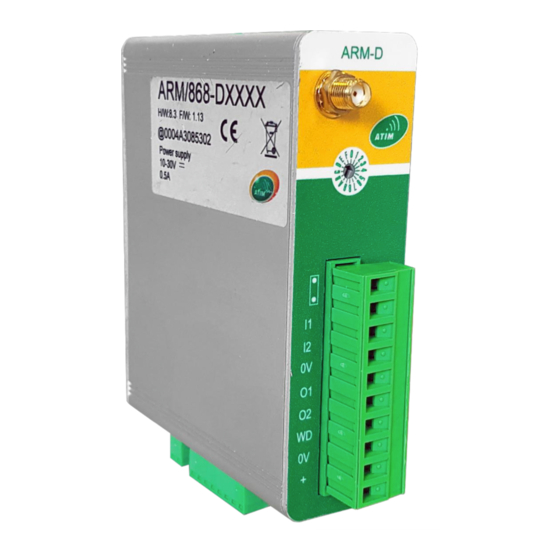
- Page 1 Advanced Radio Modules Modem Radio Digital ARM-DXXXX User Guide Concerned model: ARM/868-DXXXX...
-
Page 2: Table Of Contents
ABLE OF ONTENTS Document version history ..........................3 Disclaimer ................................3 Trademarks and copyright ..........................3 Declaration of compliance ..........................4 Environmental recommendations ........................4 Explosive atmosphere ........................4 Environment............................4 Radio 5 Versions ................................5 Operating mode ........................7 ARM/XXX-D General characteristics .................. - Page 3 Standby mode ........................34 SIGFOX mode ........................35 Mode of detection on change of state of the logical inputs: ............35 Remark ............................. 37 ACCESS TO DATA ON ATIM PLATFORM ................... 38 Mode LORAWAN........................38 Test Mode ..........................43 Maintenance ........................45 Troubleshooting ........................
-
Page 4: Document Version History
Trademarks and copyright ATIM radiocommunications®, ACW ATIM Cloud Wireless® and ARM Advanced Radio Modem® are registered trademarks of ATIM SARL in France. The other trademarks mentioned in this document are the property of their respective owners. ATIM_ARM-Dxxxx_UG_EN_V1.11... -
Page 5: Declaration Of Compliance
Declaration of compliance All ACW Atim Cloud Wireless® products comply with the regulatory requirements of the R&TTE Directive (1999/5/EC), article 3: 1 SAFETY (Article 3.1a of the 1999/5/EC Directive) NF EN60950-1 Ed. 2006/A1:2010/A11:2009/A12:2011 (health) EN62479: 2010 (power <20mW) or EN62311:2008 (power >... -
Page 6: Radio
Electrical hazard – Failure to follow the instructions presents a risk of electrocution and physical injury. Direct-current symbol WARNING: do not install this equipment near any source of heat or any source of humidity. WARNING: for your safety, it is essential that this equipment be switched off and disconnected from mains power before carrying out any technical operation on it. - Page 7 contacts) Radio cards: 868MHz / 500mW: ARM-N8LD ATIM_ARM-Dxxxx_UG_EN_V1.11...
-
Page 8: Operating Mode
1. Operating mode The ARM / 868-D modem is used for the transfer of digital or analog input outputs. While very easy to use, the ARM / 868-D is fully configurable by specific software via the USB connector. 1. ARM/XXX-D General characteristics −... - Page 9 Modem ARM/xxx-D − Opto-Isolated Positive Logic Input: − MOS Positive Logic Output − Alarm Output: MOS Positive Logic Output − Analog Input 0-20mA 12bits (Option) − Analog output 0-20mA 12bits (Option) − USB programming interface − Power supply: + 10V to + 30Vdc −...
-
Page 10: Installation
Installation During installation please observe the following instructions: WARNING: the power supply of the equipment must be connected to an electrical installation complying with the standardization in force in the country (NFC 15-100 in France). It must be equipped with protections against overcurrent, overvoltages, earth faults (maximum 16A rating). WARNING: All equipment connected to the product must conform to EN 60950-1 Ed. -
Page 11: Antenna
Figure 1: Connecting the antenna. The use of coaxial cable type RG58 (-1dB / m) is not recommended (high loss) 2.1 Antenna A bad choice of antenna can have considerable consequences on the quality of the radio link. It is important to use a suitable antenna and, if necessary, a low loss cable to place it in a slightly obstructed area. -
Page 12: Mounting On A Cabinet
2.1.1 Mounting on a cabinet A.R.M. radio modems can be supplied with a ½ wave whip antenna angled so that the antenna is positioned vertically directly on the modem. This antenna is interesting if A.R.M. is mounted in a plastic box. In this case the antenna must not be placed against a metal plate (bottom plate for example). -
Page 13: Spectrum
2.1.3 Spectrum Before installation, check if possible which radio frequencies are used nearby. 2.1.4 Distance of transmission The ARM / 868-D version extends the range to more than 10kms. 2.1.5 Radio channel selection The selection of the radio channel is done either by the USB configurator or by the encoder wheel. It is possible to use the other radio channels of the radio module other than those of the coding wheel. - Page 14 Pin 10 Do not use Pin 9 Do not use Pin 8 Digital input 1 Pin 7 Digital input 2 Pin 6 0V Power supply Pin 5 Digital output 1 Pin 4 Digital output 2 Pin 3 Alarm digital output Pin 2 0V Power supply Pin 1...
- Page 15 Analog Output The RS485 link is always wired with the daughter cards. The RS485 link is used in MODBUS mode for wired other slaves and in MIRROR mode for the addition of input output (See option with ATIM). Connector RS485...
-
Page 16: Power Supply
This must be between 10 and 30V and rectified, filtered. Beware of 220V power supply units that are often of poor quality and can deliver peaks below 9V! We recommend the use of our 24V reference ATIM power supply: ALIM220-24V-1A The power supply must be near the radio modem. -
Page 17: Rs485 Serial Link
Only qualified personnel can open the device! Do not put objects into the device. The output voltage adjustment potentiometer can only be operated with an insulated screwdriver. Do not expose the unit to fire or water. Installation instructions ➢ This power supply is designed for professional indoor systems. During operation the power supply must be inaccessible. -
Page 18: Digital Output
2.2.4 Digital output • Number 2 version ARM-D-2200 • Type: MOSFET (Positive Logic) • Voltage Range: 9 to 30Vdc • Maximum charging current: 0.5mA • Short circuit protection: 0.7A to 1.5A • Leakage current: 100μA 2.2.5 Girl card digital input •... -
Page 19: Girl Card Analogic Output
2.2.8 Girl card analogic output • Number: 1 • Type: 0-20mA • Resolution: 12bits (4095pts) • Maximum error: 0.5% PE • Power loop through the modem power ATIM_ARM-Dxxxx_UG_EN_V1.11... -
Page 20: Update And Setup
The USB connector is on the back of the modem. 3.2 Modem update Download on the ATIM website the update software: USB Bootloader. Download the program file: ARMD Vx.x On the modem put the wheel the encoder wheel on the 0... - Page 21 Lauch the updates At the end of the programming: • Turn off the power • Disconnect the USB cable • Set the encoder wheel to a position other than 0 • Wait 20s • Turn on the power (USB connector not connected) •...
-
Page 22: Setup Through The Configurator
3.3 Setup through the configurator Download the ARM-D configurator software from the ATIM website Connect the USB cable Powering LED 1 (Power) flashes (200ms / 200ms). LED 7 Rx (Green Led) flashes (20ms / 800ms) MODBUS configuration Baudrate : Radio speed: 1200bps to 115000bps for ARM-N8 radio... - Page 23 MIRROR configuration Baudrate: Radio speed: 1200bps to 115000bps for ARM-N8 radio 9600bps or 19200bps for compatible old modem ARM radio Channel: Radio Channel Selection (See USER GUIDE ARM N8LD-LP) Old ARM modem compatibility: selection from 1 to 15 Compatibility radio configuration compatible with old modem from the ARM range Coding wheel: selects the radio channel according to the position of the encoder wheel (See table) @Modem: Local address (1 to 255) @Remote: destination address (1 to 255)
-
Page 24: Mode Advanced
As a result, the LED7 (Receive / Fault) may flash or remain fixed for some time. At the end LED 1 (Power) must be fixed. If LED 7 (Receive / Fault) flashes red for several seconds, then turn off the modem and turn it back on. If the fault persists, contact ATIM. • Do not turn off the power during setup •... -
Page 25: Operating Mode
4 Operating mode 4.1 Inputs-Outputs Modbus mode access The ARMD radio modem operates in Modbus RTU slave. The Modbus frame includes (send and answer): − Slave number (8bits) (number 0 = general broadcast: all slaves no answer) − Function − data −... - Page 26 MODBUS ADDRESS TABLE DESIGNATION Address Address Multiple Hexa Decimal register access Direct digital inputs reading 0000 b0: Input 1 state b1: Input 2 state b2: Input 3 state (Girl card option position 1) b3: Input 4 state (Girl card option position 2) b4: Input 5 state (Girl card option position 3) b5: Input 6 state (Girl card option position 4) b6.b15: non used...
- Page 27 Default value 2mn (bt:200ms) Modem reset at the end of the test Do not use 0070 0071 Do not use Reading and writing of number Bloc EEPROM 0078 007F Writing $A7B5 Reset ARMD Reading and writing of memorized registers EEPROM See 0080 Command table AT à...
- Page 28 b4: Output 5 (Girl card option position 3) b5: Output 6 (Girl card option position 4) b6.b15: non used 0505 1285 Digital output reading and writing command 1 b0: Output 1 b1: Output 2 b2: Output 3 (Girl card option position 1) b3: Output 4 (Girl card option position 2) b4: Output 5 (Girl card option position 3) b5: Output 6 (Girl card option position 4)
- Page 29 0519 1305 Digital output 3 reading and writing (option) State 0: value 0000; State 1: value 00FF Digital output 4 reading and writing (option) 051A 1306 State 0: value 0000; State 1: value 00FF 051B 1307 Digital output 5 reading and writing (option) State 0: value 0000;...
- Page 30 0530 1328 Rising edge meter reading and writing INP1 (LSB) 0531 1329 Rising edge meter reading and writing INP1 (MSB) 0532 1330 Rising edge meter reading and writing INP2 (LSB) 0533 1331 Rising edge meter reading and writing INP2 (MSB) 0534 1332 Rising edge meter reading and writing INP3 (LSB)
- Page 31 0561 1377 Reserved 0562 1378 Reserved 0563 1379 Reserved 0564 1380 Reserved 0565 1381 Reserved 0566 1382 Reserved 0567 1383 Reserved 0568 1384 Reserved 0569 1385 Reserved 056A 1386 Reserved 056B 1387 Reserved 056C 1388 Reserved 056D 1389 Reserved 1390 Reserved 056F 1391...
-
Page 32: Remarks
Remarks − The memorized input corresponds to the detection of a rising edge of the corresponding logic − input, the register must be reset by a MODBUS command in order to detect a new transition − For logic outputs, the priority is first the blinking of the output, then the setting to 1. −... -
Page 33: Inputs-Outputs Mirror Mode Access
4.2 Inputs-Outputs Mirror mode access This function has 3 modes: • Simple master mirror mode: In this configuration, the master modem and the slave modem have identical configuration of the inputs and outputs, the master modem sends a radio frame representing the state of its inputs to the slave modem which copies the state of the inputs received on its outputs and which immediately returns the status of its inputs to the master modem. - Page 34 USB Advanced Mode setting: Register Used by Mirror Mode: S001: Application Register 2: B0: Mirror mode frame compatible ARM-D B1: Mirror mode frame compatible ARM-DA B2: Do not use B3: Cyclic Mode Validation B4: State change transmission of logic inputs B5: Unidirectional mode No frame between slave and master B6: Do not use B7: Do not use...
-
Page 35: Repeater Function
4.3 Repeater function Repeater mode non available Watchdog alarm The validation of the watchdog makes it possible to control the non-reception of radio frame for a given time. At the end of the determined time without radio frame detection, the modem puts its outputs in the fallback position and can activate its alarm output. -
Page 36: Sigfox Mode
SIGFOX mode The ARM/SF8-DXXXX modem is already preconfigured to access the SIGFOX network. On power-up or after a reset, the modem sends a first SIGFOX functional frame 10 seconds after the power supply, then returns 20 seconds after a second SIGFOX frame, then 30 seconds after a third frame and then the modem goes into normal operation. - Page 37 It is possible to have 4 analog inputs. The detection is done on a predefined variation in a register. The software performs a measurement of the analog inputs every 3 minutes, this time is configurable. If the value exceeds this variation, the software sends a SIGFOX frame. The modem does not go into sleep mode and must remain powered.
-
Page 38: Remark
Reception current Emission current Standby current Mode Sends cyclic analog inputs It is possible to have 4 analog inputs. The software performs a measurement of the analog inputs every 3 minutes, this time is configurable The modem cyclically sends a SIGFOX frame. The cycle time is 10mn multiple and is configurable by register. -
Page 39: Access To Data On Atim Platform
SIGFOX: Analog input trigger on variation of the value b6: SIGFOX: Analogue input periodic trigger b7: Do not use (= 0) ACCESS TO DATA ON ATIM PLATFORM Log on to the web platform http://acw.atim.com to access your devices and view your data. Your login details will be provided by email to the shipping of your order. - Page 40 On power-up or after a reset, the modem sends a first functional LORAWAN frame 10 seconds after powering on, then returns 20 seconds after a second LORAWAN frame then 30 seconds after a third frame then the modem starts up in normal operation. There are several operating modes which are independent of each other.
- Page 41 Register of configuration : o Registre S041 bit 1: Cyclic counting emission validation o Registre S042 bit 0 to 3: Edge selection of logic input 1 and 2 o Registre S041 bit 6: Counter backup o Registre S46: Cycle time (bt :10mn) LORAWAN frame: Octet 1: 0x34 Octet 2: bit0 logic input 1 state;...
- Page 42 Note The alarm function is not available in this mode The Sleep Mode function can be used in some modes. While in standby mode, the Power LED blinks for a few milliseconds every 16 seconds. The registers used are: o Register S040 bit 1: sleep mode validation o Register S065-S064: standby time (bt : 16s) Ex : about 15mn S65=00 S64=56 Consumption is about 3 mA in standby mode.
- Page 43 LORAWAN: Analog input triggering on variation of the value b6: LORAWAN: Analog input periodic trigger b7: Do not use (=0) ACCES AUX DONNEES SUR PLATEFORME ATIM Connect to the web platform http://acw.atim.com to access your devices and view your data. Your login details will be provided to you by email when your order is shipped.
-
Page 44: Test Mode
5 Test Mode The test mode can be activated either by MODBUS request or by using the USB configurator in the ADVANCED mode. In the ADVANCED mode write to the address 192 by setting the value of the test. In the MODBUS mode write the test value to 0x60 (see MODBUS table). To exit the test modem the power supply of the ARM-D modem must be disconnected. - Page 45 Test E Do not use Test F Do not use ATIM_ARM-Dxxxx_UG_EN_V1.11...
-
Page 46: Maintenance
As a result, the LED7 (Receive / Fault) may flash or remain fixed for some time. At the end LED 1 (Power) must be fixed. If LED 7 (Receive / Fault) flashes red for several seconds, then turn off the modem and turn it back on. If the fault persists, contact ATIM. ATIM_ARM-Dxxxx_UG_EN_V1.11... - Page 47 TABLE OF MODEM ARMD CONFIGURATION REGISTERS The values of the registers are in hexadecimal format: $ xx Register use Default value 008A Registry Application 1: see detail 0x02 008B Registry Application 2: see detail 0x00 008C Radio: Radio Channel Number (LSB) 0x0A 008D Radio: Radio Channel Number (MSB)
- Page 48 00AA Do not use 00AB Do not use 00AC Registry Application 3: see detail 0x59 00AD Registry Application 4: see detail 0x00 00AE Do not use 00AF Do not use 00B0 Do not use 00B1 Do not use 00B2 Registry Application 6: see detail 0x60 00B3 Do not use...
- Page 49 Do not use 00D4 Do not use 00D5 Do not use 00D6 Do not use 00D7 Do not use 00D8 Do not use 00D9 Do not use 00DA Do not use 00DB Do not use 00DC Do not use 00DD 00DE Do not use Do not use...
- Page 50 Application register 1: S00 (MODBUS address: 0x8A) b0 – b3 : 0 Do not use 1. Do not use 2. ModBus mode 3. Simple master mirror mode 4. Do not use 5. Slave mirror mode 6. Slave mirror mode 7. Progammation mode 8.
- Page 51 Application register 6: S40 (MODBUS address: 0xB2) b0: Do not use (=0) b1: Do not use (=0) b2: Do not use (=0) b3: Do not use (=0) b4: Do not use (=0) b5: Radio: ARM compatibility validation b6: Radio: Validation Encoder Wheel b7: Do not use (=0) Warning Any modification of the configuration parameters causes a modification of the current program.
-
Page 52: Troubleshooting
Check whether the modem has been registered on the network • Check whether Tx and Rx lights are flashing when emission or reception 8 Technical support For any information or technical problems, you can contact our technical support on this page: https://www.atim.com/en/technical-support/ ATIM_ARM-Dxxxx_UG_EN_V1.11...
Need help?
Do you have a question about the ARM-D Series and is the answer not in the manual?
Questions and answers