Advertisement
Quick Links
Ω
Audio
Creative
DDDAC1794
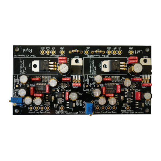
Finally !! The new, highly improved '2016' DDDAC1794 module! De voltage regulation at
the analog side of the system has now an embedded Tentlabs Shunt regulator. The Bias
through the much discussed 'pin 20' got a constant current source (CCS) which replaces
the fixed 6K1 resistor. All resulting in the next stage of superb sound reproduction
Version 1.1
1
Advertisement

Summary of Contents for Audio Creative DDDAC1794
- Page 1 Creative DDDAC1794 Finally !! The new, highly improved ‘2016’ DDDAC1794 module! De voltage regulation at the analog side of the system has now an embedded Tentlabs Shunt regulator. The Bias through the much discussed ‘pin 20’ got a constant current source (CCS) which replaces the fixed 6K1 resistor.
- Page 2 Ω Audio Creative DDDAC1794 Few tips before the work starts... Of course you will need a good soldering station. Use one with variable temperature or at least one with a thermostat to keep the temperature constant. Keep the tip clean by wip- ing every time across a wet sponge.
- Page 3 Ω Audio Creative DDDAC1794 The construction We will start with soldering the resistors. Important point: do not place the 6k1 resistor. ONLY when you want to experiment with ‘pin 20’ by not using the CCS, in which case you should NOT install the trimmer and 100Ohm resistors… The SMD parts are already mount- ed so you only have to install the resistors and trimmer.
- Page 4 Ω Audio Creative DDDAC1794 Let’s start... First we solder the two 4,7 Ohm resistors on the PCB ... The bending tool, see picture above, is a very handy tool to make a perfect fit. The PCB has exact this distances.
- Page 5 Ω Audio Creative DDDAC1794 Than solder the two 100Ohm resistors. Heat it well and take the time needed to have the solder flow nicely. Cut the wires and you might want to re-heat /re-solder shortly the connections, so it even...
- Page 6 Ω Audio Creative DDDAC1794 Capacitors Next we will solder the 18 pcs of the 100nF capacitors. Best is to put them on the pcb and slightly bend the two wires to the outside so they will not fall off the board anymore.
- Page 7 Ω Audio Creative DDDAC1794 It will look like this at this stage...
- Page 8 Ω Audio Creative DDDAC1794 The electrolytic capacitors (elcos) There are 12 pcs of the 10uF and 2 pcs of the 47uF Elcos to be mounted. When placing the elcos make sure (check AND double check) that the polarization (plus and minus wires) are correct!
- Page 9 Ω Audio Creative DDDAC1794 Again, take your time to let the solder flow. Specially the “minus” poles are at the ground plane which will attract quite some heat in the first few seconds when the solder tip is placed. So do not “bake” the solder on the pads. Let it flow.
- Page 10 Ω Audio Creative DDDAC1794 Specially here it make sense to cut very short (2mm above PCB area) and (optionally) resolder the connections. If more modules are mounted above each other we must avoid that long wires sticking out are shortcutting against the capacitores on the below deck.
- Page 11 Ω Audio Creative DDDAC1794 In between view of the PCB The voltage regulators Before mounting we bend the pins with the platbek tang. Directly after the thicker part of the pins.
- Page 12 Ω Audio Creative DDDAC1794 Press the connection pins through the PCB. Solder the middle pin with a small drop while making sure the voltage regulator is nicely placed on the PCB. (See image).
- Page 13 Ω Audio Creative DDDAC1794 Here it is best to cut the wires first a few mm above the PCB and than solder the two out- side pins. Do not forget to re-solder the middle pin... Trimmers As you can see, the only thing missing are the two blue multi turn trimmers for the CCS...
- Page 14 Ω Audio Creative DDDAC1794 Place the trimmers in the correct holes and bend the wires a little bit to the outside. Solder the wires and cut them short. The adjusting of the CSS can only be done after the dac module is installed on the main board.
- Page 15 Unless we tried to be as clear and complete as possible in this con- struction manual, we cannot exclude that still something is unclear. In that case just email Audio Creative or DDDAC for further help! Also feedback to improve on text or image is more than welcome...
Need help?
Do you have a question about the DDDAC1794 and is the answer not in the manual?
Questions and answers