
Subscribe to Our Youtube Channel
Related Manuals for Elenos T25000


Summary of Contents for Elenos T25000
- Page 1 BROADCAST EQUIPMENT Via G. Amendola 9 44028 Poggio Renatico Ferrara - Italy Tel : +39 532 829 965 Fax : +39 532 829 177 E-mail: info@elenos.com support@elenos.com Web Site: http://www.elenos.com...
- Page 2 Hand Book T25000 - The constructor reserves the right to modify the information in this manual at any time without advising update. 2000 Elenos S.r.l. Printed in Italy Cod. MAN0034 21/10/1996 Preliminary mater in English 23/10/2000 Rev. 1 Technical Office TEL: +39 532 829 965 FAX: +39 532 829 177...
-
Page 3: Table Of Contents
Hand Book T25000 - SUMMARY DESCRIPTION....................... 5 TECHNICAL FEATURES .................... 7 TECHNICAL DESCRIPTION ..................8 USER INTERFACE AND LOGIC OF OPERATION..........9 FRONT PANEL ......................13 FIRST PHASE OF INSTALLATION ................ 14 INSTALLATION OF THE THERMIONIC TUBE..........17 SECOND PHASE OF INSTALLATION ..............18 ACTIVATION OF THE TRANSMISSION SYSTEM .......... - Page 4 Hand Book T25000 - Layout E20127 ......................45 Electrical diagram E20127 ( 1 of 6)................46 Part list E20127......................52 Layout E20128 ......................61 Electric diagram E20128....................62 Part list E20128......................63 Layout E20131 ......................64 Electric diagram E20131....................65 Part list E20131......................
-
Page 5: Description
Hand Book T25000 - DESCRIPTION The T25000 is an amplifier for the transmission of frequency modulation (total deviation 150 KHz) using a thermionic tube in an amplifying cavity with adjustable input and output frequency tuning. Conceived as the final stage in a transmission system, it requires a modulator and other intermediate stages of amplification housed in the same or separate mechanical structure. - Page 6 Hand Book T25000 - Technical Office TEL: +39 532 829 965 FAX: +39 532 829 177...
-
Page 7: Technical Features
Hand Book T25000 - TECHNICAL FEATURES DESCRIPTION 10000W OUT 25000W OUT THERMOIONICS TUBE TYPE TRIODE EIMAC 3CX15000 EXPECTED TUBE 20000 HOURS 10000 HOURS POWER OUTPUT 25000 WATT EXCITATION POWER 650W 1700W REFLECTED POWER 750W 300W S.W.R. 750 WATT POWER GAIN Ca. -
Page 8: Technical Description
Hand Book T25000 - TECHNICAL DESCRIPTION The T25000 unit is composed of various functional elements: power amplifying cavity which houses the thermionic tube, (this is a triode with direct cathode heating, configured in common grid mode with input signal to the cathode and output from the anode); low-pass output filter for the suppression of harmonic components of the carrier frequency;... -
Page 9: User Interface And Logic Of Operation
Hand Book T25000 - USER INTERFACE AND LOGIC OF OPERATION The display of all controls and operational parameters are situated on the unit's front panel. Any suspension of operation, whether temporary or indefinite, results in the thermionic tube's HT anode supply being shut down and the disabling of the modulator's supply. - Page 10 Hand Book T25000 - The ON indicator light indicates that the T25000 is powered by the line supply. The flashing SAFETY light indicates that the equipment is not in a safe condition to operate at high voltage and is thus in a protection state. This happens when a panel is open or an important electrical connector is not inserted correctly.
- Page 11 Hand Book T25000 - transformer sensor detects that normal temperatures have been restored. The most probable causes of this anomaly are excessive ambient temperatures, or inefficient air filters. The flashing UNDER PRESSURE light indicates that the pressure of cooling air within the amplifying cavity is insufficient.
- Page 12 They will be extinguished when the T25000 power stage is faulty or has been shutdown by the operator. An hour counter is located on the front panel which registers the number of hours that the unit has been connected to the line supply.
-
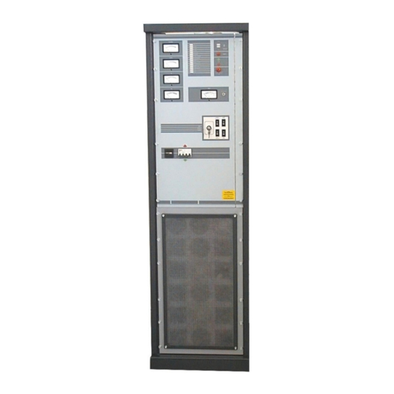
Page 13: Front Panel
Hand Book T25000 - FRONT PANEL Technical Office TEL: +39 532 829 965 FAX: +39 532 829 177... -
Page 14: First Phase Of Installation
If the T25000 is the largest source of heat of the entire system, and if the ambient temperature is 25°C, at least 2000m³ per hour should be removed. If the temperature is 45°C then at least 3000m³ per hour should be evacuated. - Page 15 Make absolutely certain that this earth conductor is connected to the earth terminal of the whole T25000 unit. Do not connect the central node of the star of the transformer primary to the neutral of the line supply. Connect the anode transformer primary to the intended, heavy-section cables with the terminals best suited for high voltage operation (see the diagram for three-phase connection).
- Page 16 RF input of any second intermediate stage. The RF output of the unit preceding the final T25000 amplifier is connected to the input of the low- pass filter which finally supplies the input of the final amplifying cavity. The RF connection is complete when the power output of the T25000 is connected to the radiating system.
-
Page 17: Installation Of The Thermionic Tube
Hand Book T25000 - INSTALLATION OF THE THERMIONIC TUBE When the T25000 amplifier is in its final position, installation of the thermionic tube may proceed. The directions which follow are also valid for periodic replacement of the thermionic tube; for this reason it is a good idea to leave a copy of the technical manual available nearby. -
Page 18: Second Phase Of Installation
Arrange all the other transmission system apparatus in their final positions. Included with the T25000 unit is a kit of sleeves made from material which are used to close the three wide access points which correspond to the entrance and exits of the RF cables and the hot air exit. The application of the three sleeves is clear, their function is to prevent the ingress of insects or organic vegetable material into the equipment. -
Page 19: Activation Of The Transmission System
ST BY position (advised). Switch on the three phase equipment to check for correct rotation of the three phase cooling fans. In the case of the T25000, if the connection of the three phases is correct, 3 seconds after switch-on, the UNDER PRESSURE indicator, located on the front panel, will go out. -
Page 20: Tuning Instructions
Hand Book T25000 - TUNING INSTRUCTIONS NOTE: The T25000 unit is factory-adjusted (if no other request has been made) to operate at 98MHz. The tuning adjustments are motorised and controlled by 4 controls (UP/DOWN) on a switchboard located on the front panel. Two choices are available: FAST adjustment and SLOW adjustment, depending on the position of the selector key on the front panel. - Page 21 ANODE TUNING (top right) to maximise the relative power output and thus the electrical efficiency of the T25000. These instructions refer to output tuning, however it will be necessary, during this procedure, to also optimise the input tuning in order to minimise the reflected power reading of the driver stage.
-
Page 22: Operational Limits
Hand Book T25000 - OPERATIONAL LIMITS The T25000 power amplifier can function at full power if the ambient conditions fall within the limits defined in the chapter entitled "First Phase of Installation". The maximum altitude of the installation must not exceed 2000m above sea level to guarantee maximum RF power output. If the altitude of the installation does exceed 2000m, the specified RF power output must be reduced, also in correlation with the ambient temperature. -
Page 23: Periodic Maintenance
This is essential mainly if the radiating system is suffering adversely from the external ambient conditions. Several parts of the T25000 are employed in the filtering of the cooling air; depending on the relative ambient conditions, the anti-dust filters will need replacing at intervals dependant on the quality of air in the area. -
Page 24: Adjustment Of The Filament Voltage
ADJUSTMENT OF THE FILAMENT VOLTAGE The filament of the thermionic tube installed in the T25000 is powered by an AC stabilised circuit with a precision of better than 1.5%. The filament voltage has a very important influence on the operational life of the thermionic tube, that is, the lower the voltage, the longer the life of the tube. -
Page 25: Remarks On Electrical Diagrams
Hand Book T25000 - REMARKS ON ELECTRICAL DIAGRAMS We in these notes explain how interpret the electrical schemes that follows this page. All electronic components are installed on various mechanical panels, a drawing shows their positions with a reference label. A special drawing represents the frontal panel and helps to find the various warning indications and status conditions of the machinery. -
Page 26: Line Voltage Diagram Connection
Hand Book T25000 - LINE VOLTAGE DIAGRAM CONNECTION Technical Office TEL: +39 532 829 965 FAX: +39 532 829 177... -
Page 27: Part List Transmitter 20K
Hand Book T25000 - PART LIST TRANSMITTER 20K Sheet # 1 Part List of Sheet # 1 Sheet # 2 Part List of Sheet # 2 Sheet # 3 Part List of Sheet # 3 Sheet # 4 Part List of Sheet # 4... -
Page 28: Sheet # 1
Hand Book T25000 - Sheet # 1 Technical Office TEL: +39 532 829 965 FAX: +39 532 829 177... -
Page 29: Part List Of Sheet # 1
Hand Book T25000 - Part list of Sheet # 1 Terminals array 1 6 contact + 5 with fuse Terminals array 1 8 contact Main Switch 380 V 25 A Switch HT 1 400V 3-Phase 45 KW Switch HT 2 400V 3-Phase 45 KW T. -
Page 30: Sheet # 2
Hand Book T25000 - Sheet # 2 Technical Office TEL: +39 532 829 965 FAX: +39 532 829 177... -
Page 31: Part List Of Sheet # 2
Hand Book T25000 - Part list of Sheet # 2 Therminals Array 1 1 Contat SW1 ..SW8 Connector Security Wire Resistor 50x400 60 ohm Wire Resistor 50x400 60 ohm Wire Resistor 50x400 60 ohm Wire Resistor 50x400 60 ohm... -
Page 32: Sheet # 3
Hand Book T25000 - Sheet # 3 Technical Office TEL: +39 532 829 965 FAX: +39 532 829 177... -
Page 33: Part List Sheet # 3
Hand Book T25000 - Part list sheet # 3 Wire Resistor 35x100 20 ohm Wire Resistor 35x100 20 ohm Wire Resistor 35x100 20 ohm Meas-Tranf Transformer 1:1 {20V/20V} Filament Transformer 2 KVA CN100 AMP cylinder connector 24 pin Technical Office TEL: +39 532 829 965 FAX: +39 532 829 177... -
Page 34: Sheet # 4
Hand Book T25000 - Sheet # 4 Technical Office TEL: +39 532 829 965 FAX: +39 532 829 177... -
Page 35: Part List Sheet # 4
Hand Book T25000 - Part list sheet # 4 MOV 1 MOV type S20K-275 MOV 2 MOV type S20K-275 MOV 3 MOV type S20K-275 MOV 4 MOV type S20K-275 MOV 5 MOV type S20K-275 MOV 6 MOV type S20K-275 MOV 7... -
Page 36: Sheet # 5
Hand Book T25000 - Sheet # 5 Technical Office TEL: +39 532 829 965 FAX: +39 532 829 177... -
Page 37: Part List Sheet # 5
Hand Book T25000 - Part list sheet # 5 M eter 100uA f.s. M 3D R.PWR M eter 100uA f.s. M 3D TEST M eter 100uA f.s. M 3D M eter 100uA f.s. M 3D M eter 100uA f.s. M 3D S.T. -
Page 38: Sheet # 6
Hand Book T25000 - Sheet # 6 Technical Office TEL: +39 532 829 965 FAX: +39 532 829 177... -
Page 39: Part List Sheet # 6
Hand Book T25000 - Part list sheet # 6 Resistor 0.25W Resistor 0.25W 2700 Resistor 0.25W Resistor 0.25W 18 K Resistor 0.25W 49.9 Resistor 0.25W 6980 Resistor 0.25W 6980 Trimmer type 67WR200K TR11 Trimmer type 67WR20K Ceramic F.P. Capacitor 3 pF... -
Page 40: Sheet # 7
Hand Book T25000 - Sheet # 7 Technical Office TEL: +39 532 829 965 FAX: +39 532 829 177... -
Page 41: Part List Sheet # 7
Hand Book T25000 - Part list Sheet # 7 Bridge type KBPC250G Tuning Output Motor Motor type 36.10.5 Coupling Output Motor Motor type 36.10.5 Tuning Input Motor Motor type 36.10.5 Coupling Input Motor Motor type 1.61.013.325 Anode Tuning Switch Switch Togle 2-Way 3-Pos. 131FL Anode Impedance Switch Switch Togle 2-Way 3-Pos. -
Page 42: Layout E20123.3
Hand Book T25000 - Layout E20123.3 Cathode bias and signals conveyor board Technical Office TEL: +39 532 829 965 FAX: +39 532 829 177... -
Page 43: Electrical Diagram E20123.3
Hand Book T25000 - Electrical diagram E20123.3 Technical Office TEL: +39 532 829 965 FAX: +39 532 829 177... -
Page 44: Part List E20123.3
Hand Book T25000 - Part list E20123.3 Resistor 0.25W 100K Resistor 0.25W Resistor 0.25W 49.9 Resistor 0.25W 49.9 Resistor 0.25W 49.9 Resistor 0.12 Resistor 0.12 Resistor 0.12 Resistor 0.12 Resistor 0.25W 49.9 Resistor 0.25W Resistor 0.25W 49.9 Resistor 0.12 Resistor 0.12... -
Page 45: Layout E20127
Hand Book T25000 - Layout E20127 General control board layout Technical Office TEL: +39 532 829 965 FAX: +39 532 829 177... -
Page 46: Electrical Diagram E20127 ( 1 Of 6)
Hand Book T25000 - Electrical diagram E20127 ( 1 of 6) Technical Office TEL: +39 532 829 965 FAX: +39 532 829 177... - Page 47 Hand Book T25000 - Electrical diagram E20127 ( 2 of 6) Technical Office TEL: +39 532 829 965 FAX: +39 532 829 177...
- Page 48 Hand Book T25000 - Electrical diagram E20127 ( 3 of 6) Technical Office TEL: +39 532 829 965 FAX: +39 532 829 177...
- Page 49 Hand Book T25000 - Electrical diagram E20127 ( 4 of 6) Technical Office TEL: +39 532 829 965 FAX: +39 532 829 177...
- Page 50 Hand Book T25000 - Electrical diagram E20127 ( 5 of 6) Technical Office TEL: +39 532 829 965 FAX: +39 532 829 177...
- Page 51 Hand Book T25000 - Electrical diagram E20127 ( 6 of 6) Technical Office TEL: +39 532 829 965 FAX: +39 532 829 177...
-
Page 52: Part List E20127
Hand Book T25000 - Part list E20127 Resistor 1300 0.25 W Resistor 2000 0.25 W Resistor 1300 0.25 W Resistor 2000 0.25 W Resistor 34 K 0.25 W Resistor 0.25 W Resistor 1020 0.25 W Resistor 0.25 W Resistor 1020 0.25 W... - Page 53 Hand Book T25000 - Part list E20127 Resistor 0.25 W Resistor 0.25 W Resistor 0.25 W Resistor 0.25 W Resistor 0.25 W Resistor 10 M 0.25 W Resistor 0.25 W Resistor 0.25 W Resistor 3.3K 0.25 W Resistor 10 M 0.25 W...
- Page 54 Hand Book T25000 - Part list E20127 R109 Resistor 0.25 W R110 Resistor 10 K 0.25 W R111 Resistor 10 K 0.25 W R112 Resistor 10 K 0.25 W R113 Resistor 100 K 0.25 W R114 Resistor 0.25 W R115...
- Page 55 Hand Book T25000 - Part list E20127 R161 Resistor 100 K 0.25 W R162 Resistor 10 K 0.25 W R163 Resistor 0.25 W R164 Resistor 15 K 0.25 W R165 Resistor 15 K 0.25 W R166 Resistor 10 K 0.25 W...
- Page 56 Hand Book T25000 - Part list E20127 Ceramic Capacitor 33 pF Ceramic Capacitor 4.7 nF Ceramic Capacitor 4.7 nF Ceramic Capacitor 4.7 nF Ceramic Capacitor 4.7 nF Ceramic Capacitor 4.7 nF Ceramic Capacitor 4.7 nF Ceramic Capacitor 4.7 nF Ceramic Capacitor 4.7 nF...
- Page 57 Hand Book T25000 - Part list E20127 Ceramic Capacitor 4.7 nF Electr. Vert. Capacitor 10 uF Ceramic Capacitor 100 nF Electr. Vert. Capacitor 10 uF Ceramic Capacitor 100 nF Electr. Vert. Capacitor 1000 uF Mylar Capacitor 100 nF Electr. Vert. Capacitor 10 uF Electr.
- Page 58 Hand Book T25000 - Part list E20127 C114 Ceramic Capacitor 100 nF C115 Electr. Vert. Capacitor 10 uF C116 Electr. Vert. Capacitor 10 uF C117 Electr. Vert. Capacitor 10 uF C118 Electr. Vert. Capacitor 10 uF C119 Electr. Vert. Capacitor...
- Page 59 Hand Book T25000 - Part list E20127 Diode type 1N4148 Diode type 1N4148 Diode type 1N4148 Diode type 1N4148 Diode type 1N4148 Diode type 1N4148 Diode type 1N4148 Diode type 1N4148 Diode type 1N4148 Diode type 1N4148 Diode type 1N4007...
- Page 60 Hand Book T25000 - Part list E20127 IC25 I.C. type LM7912 case TO220 + Heatsink 21C / W Jumper 2 pin Jumper 2 pin Jumper 2 pin Jumper 2 pin Jumper 2 pin Relay Finder type 40.31 Relay Finder type 40.31 Relay Finder type 40.31...
-
Page 61: Layout E20128
Hand Book T25000 - Layout E20128 Technical Office TEL: +39 532 829 965 FAX: +39 532 829 177... -
Page 62: Electric Diagram E20128
Hand Book T25000 - Electric diagram E20128 Technical Office TEL: +39 532 829 965 FAX: +39 532 829 177... -
Page 63: Part List E20128
Hand Book T25000 - Part list E20128 PCB1 Board E20128.3 Resistor ELENOS 5% Resistor 0.25 W Resistor 49.9 0.25 W Paper Capacitor 0.1 uF 1000 V +/- 5% MOV1 MOV type S20K-275 MOV2 MOV type S20K-275 MOV3 MOV type S20K-275... -
Page 64: Layout E20131
Hand Book T25000 - Layout E20131 Technical Office TEL: +39 532 829 965 FAX: +39 532 829 177... -
Page 65: Electric Diagram E20131
Hand Book T25000 - Electric diagram E20131 Technical Office TEL: +39 532 829 965 FAX: +39 532 829 177... -
Page 66: Part List E20131
Hand Book T25000 - Part list E20131 PCB1 Print Board type E20131 Resistor 0.25W Resistor 0.25W Resistor 0.25W Resistor 0.25W Resistor 0.25W Resistor 0.25W Resistor 0.25W Resistor 0.25W Resistor 0.5W Resistor 0.5W Resistor 0.5W Resistor 0.5W Resistor 0.5W Resistor 0.5W Resistor 0.5W... - Page 67 Hand Book T25000 - Part list E20131 Ceramic Capacitor 100nF Vert. Electr. Capacitor 10uF Ceramic Capacitor 4.7nF Ceramic Capacitor 100nF Ceramic Capacitor 100nF Vert. Electr. Capacitor 10uF Ceramic Capacitor 4.7nF Diode type 1N4007 Diode type 1N4007 Diode type 1N4007 Diode type 1N4007...
-
Page 68: E20138
Hand Book T25000 - E20138 Technical Office TEL: +39 532 829 965 FAX: +39 532 829 177... -
Page 69: Part List E20138
Hand Book T25000 - Part list E20138 Technical Office TEL: +39 532 829 965 FAX: +39 532 829 177... -
Page 70: E20144
Hand Book T25000 - E20144 Technical Office TEL: +39 532 829 965 FAX: +39 532 829 177... -
Page 71: Part List E20144
Hand Book T25000 - Part list E20144 PCB1 Board E20144.0 Diode type A12FR120 Diode type A12F120 Diode type A12FR120 Diode type A12F120 Diode type A12FR120 Diode type A12F120 Diode type A12FR120 Diode type A12F120 Diode type A12FR120 Diode type A12F120... -
Page 72: E20139
Hand Book T25000 - E20139 - Interface board (optional) Technical Office TEL: +39 532 829 965 FAX: +39 532 829 177... -
Page 73: Part List E20139
Hand Book T25000 - Part List of E20139.1 Board Rif. Description Value Remarks Board Code 2PCB0177 R1 - R8 Resistor 0.25 W 1% Ceramic Capacitor 5mm 4.7 nF Electrolytic vert. Capacitor 10 uF C3,C4,C5 Ceramic Capacitor 5mm 4.7 nF C6, C7...
Need help?
Do you have a question about the T25000 and is the answer not in the manual?
Questions and answers