Sign In
Upload
Download
Table of Contents
Contents
Add to my manuals
Delete from my manuals
Share
URL of this page:
HTML Link:
Bookmark this page
Add
Manual will be automatically added to "My Manuals"
Print this page
×
Bookmark added
×
Added to my manuals
Manuals
Brands
Unico Manuals
Air Handlers
V2430
Installation manual
Unico V2430 Installation Manual
Vertical ahu
Hide thumbs
1
Table Of Contents
2
3
4
5
6
7
8
9
10
11
12
13
14
15
page
of
15
Go
/
15
Contents
Table of Contents
Bookmarks
Table of Contents
Table of Contents
Mounting
Location
Duct Connection
Air Filtration
Piping
Sequence of Operation
Checking Airflow
Charging a Cooling System
Charging a Heat Pump System
Advertisement
Quick Links
1
Table of Contents
2
Duct Connection
3
Piping
Download this manual
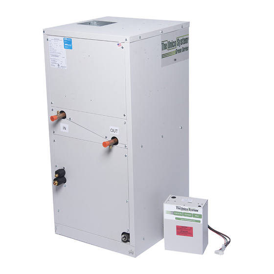
VERTICAL AHU
INSTALLATION MANUAL
BULLETIN 30-015.003
Table of
Contents
Previous
Page
Next
Page
1
2
3
4
5
Advertisement
Table of Contents
Need help?
Do you have a question about the V2430 and is the answer not in the manual?
Ask a question
Questions and answers
Related Manuals for Unico V2430
Air Handlers Unico V3036 Installation Manual
Vertical ahu (15 pages)
Air Handlers Unico M Series Installation Manual
(23 pages)
Air Handlers Unico M Series Installation Manual
Modular air handler units (28 pages)
Air Handlers Unico M Series Installation Manual
Slide-in heating coil (6 pages)
Air Handlers Unico M Series Installation Manual
Air handler unit (26 pages)
Air Handlers Unico M Series Installation Manual
(29 pages)
Air Handlers Unico M Series Installation Manual
(37 pages)
This manual is also suitable for:
V3036
V3642
Table of Contents
Print
Rename the bookmark
Delete bookmark?
Delete from my manuals?
Login
Sign In
OR
Sign in with Facebook
Sign in with Google
Upload manual
Upload from disk
Upload from URL


Need help?
Do you have a question about the V2430 and is the answer not in the manual?
Questions and answers