Table of Contents
Advertisement
Quick Links
Advertisement
Table of Contents

Summary of Contents for NRG Systems TallTower 34 m
- Page 1 NRG 34 m TallTower™ Installation Manual & Specifications Global leader in wind measurement technology 110 Riggs Road · Hinesburg · VT 05461 USA · TEL (802) 482-2255 · FAX (802) 482-2272 · EMAIL sales@nrgsystems.com NRG_34m_TallTower_Installation_Manual_and_Specifications_Rev_1.05.docx 19 April 2011...
- Page 2 Specifications are subject to change without notice. NRG_34m_TallTower_Installation_Manual_and_Specifications_Rev_1.05.docx 19 April 2011...
- Page 3 Installation of guyed towers is inherently dangerous. To minimize risks, read and follow the tower installation instructions explicitly. Do not install during an electrical storm. Installation in agricultural areas may pose a threat to low flying crop dusting aircraft. Notify appropriate parties and install warning devices as needed. We assume no responsibility or liability in connection with any act, error, omission, or for any injury, loss, accident, delay, inconvenience, irregularity or damage related to any TallTower installation.
-
Page 4: Table Of Contents
Table of Contents WARNINGS ........................... 6 Do these things: ..........................6 Do NOT do these things: ........................7 Introduction ..........................8 TallTower History ..........................8 Construction and Assembly ....................... 8 Required Parts to Erect Tower System ....................8 Experience Required .......................... 8 Tower Lift Crew .......................... - Page 5 Ginpole Tilt-Up ........................... 30 Confirm all lifters and shackles are secure ..................30 Lift the ginpole ..........................30 Tower Tilt-Up ..........................31 Understanding Guy Wire Tensioning While Raising TallTower (Do not raise the tower yet) ... 31 Adjusting Guy Wires (the “Inchworm” method) ................31 Loosening Guy Wires ............................
-
Page 6: Warnings
WARNINGS Do these things: Read and follow the Tower Installation Manual! Determine the soil type at your site and install the correct anchors. Place tower anchors according to anchor manufacturer‟s recommendations. Properly ground the tower electrically. Stand to the side of any tensioned cables. Thoroughly understand tower erection procedure before beginning installation. -
Page 7: Do Not Do These Things
Do NOT do these things: DO NOT climb this tower. DO NOT erect tower within 1 ½ times the tower height of electric power lines. DO NOT install this tower during an electrical storm. DO NOT erect tower within 1 ½ times the tower height of walkways, roads, or buildings. DO NOT permit unauthorized personnel onto the site while the tower is being installed. -
Page 8: Introduction
Introduction TallTower History NRG TallTowers™, the original tilt-up tubular towers, were first introduced in 1982 and soon became the industry standard to quickly and easily get sensors up and into the wind to start measurements. TallTowers are delivered in complete kits, assembled on the ground and then tilted up and secured with guy wires. Construction and Assembly The NRG TallTower™... - Page 9 Hand sledge (for ground rods) Small adjustable wrench (for opening/closing acorn clamps) Small pliers (for sensor cotter pins) Small Phillips head (+) screwdriver (for set screws) Flat (-) screwdriver (for antenna mounting assembly) Knives (to cut electrical tape) – one per crew member ...
-
Page 11: Unpack Your Tower
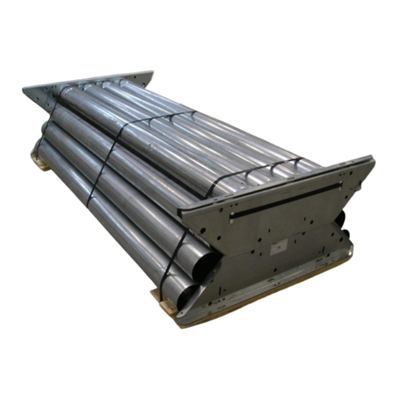
Unpack your tower Description of the packaging The 34 m TallTower packaging was designed to reduce cardboard waste, protect the tower components and allow for more economical shipment. All the tower components including anchors and ground kit are now included in one package. -
Page 12: Access And Orientation
Access and Orientation Ideally, you will want access to both ends of the packaging to unpack the contents. If a forklift is available, that is also ideal. Remove the 34 m TallTower package from the truck with the forklift and set it on an unobstructed flat area before unpacking. - Page 13 With the nut driver (or powered screwdriver), remove the 4 wood screws that fasten each end plate assembly down to the wood pallet. Set aside the 2 end plate assemblies. If you can only remove one end plate assembly, that is OK. Remove the end plate and set aside.
-
Page 14: Site Layout
Site Layout Pre-installation Planning It is a good idea to visit the site before you order your wind measurement system. You will need to make arrangements regarding how to unload your tower system. Some site preparation may also be necessary. During the first lift of a tower, the many slip joints will settle to the full engagement. - Page 15 Figure 3: Site Layout Map (bird’s eye view) NOTE: TallTowers can be installed on slopes up to 10°. When laying out a TallTower installation on a slope, measure the calculated distances along the ground to place the anchors. It is not necessary to compensate for the slope.
-
Page 16: Tower Assembly
Tower Assembly Assemble the Baseplate The baseplate will be located according to the site layout map described in the previous section. It is often easiest to assemble the baseplate in this location. Assemble 4 of the 6 large triangular baseplate sections as shown below, inserting (8) 5/16”... - Page 17 Install the gussets (4) as shown below. Be sure to install the gusset bolts with the carriage bolt head away from the gussets. Tighten all bolts in the baseplate. At the beginning of a lift, particularly for the gin pole, the winch forces are largely horizontal. These forces tend to slide the baseplate toward the winch and/or tip the baseplate up on edge.
- Page 18 Rods driven through the baseplate into the soil – With firm, deep soil, drive several pieces of rebar through the holes in baseplate into the soil. Angle them away from the winch and place as many as practical along the baseplate front edge (farthest from the winch).
-
Page 19: Install The Anchors
Install the Anchors See Appendix B: Anchoring Guidelines at the end of this manual for more information on installing anchors. Depending on the soil type, anchoring can take varying levels of planning, effort and time. Be sure to know what soil types you are dealing with as part of your pre-installation planning process. -
Page 20: Install The Base Tube
Install the Base Tube Identify the base tube. The base tube has a hole drilled through the flared (wider) end. Attach the base tube to the baseplate using the ¾” x 8” bolt through the lower holes in the center of the baseplate sides. Secure the bolt with the provided nut. -
Page 21: Attach Sensors And Booms
Attach sensors and booms Assemble the sensors, sensor boots and sensor signal cables to the booms. Wrap the sensor signal cables to the boom as shown below. Secure with weather rated electrical tape such as Scotch Super 88. Secure the booms to the tower with the supplied hose clamps. -
Page 22: Attach The Guy Wires
Attach the Guy Wires Organize and layout the lifters and guy wires Sort out and identify the guy wires and place three sets at each guy ring level. These guy wires are all the same length and are interchangeable. Sort out and identify each lifter wire. The lifter wires are NOT interchangeable. The lifter wires are color coded and are assigned to the guy ring shown in the table below. - Page 23 CORRECT Do not un-spool cable off the side of the coil as shown below. The Hankmaster can be used to roll the guy wires out to the anchors. See Appendix F for instructions for building and using a Hankmaster. NRG_34m_TallTower_Installation_Manual_and_Specifications_Rev_1.05.docx 19 April 2011...
-
Page 24: Secure Guy Wires To The Anchors
Pass the split rings through the eye of each shackle bolt to keep the shackle pins from loosening. Secure guy wires to the anchors Secure guy wires to the back and side anchors by threading the cable through the anchor loop and clamping the cable onto itself using 3 wire rope clips. -
Page 25: Assemble The Gin Pole
Assemble the Gin Pole Layout the ginpole tubes Identify the ginpole and helper ginpole tubes and hardware. Refer to the Glossary in Appendix D for pictures and descriptions of ginpole parts. Attach the ginpole base tube to the baseplate The ginpole base tube will lie on top of the tower base tube. Place the ginpole base tube with hole between the baseplate‟s vertical channels. -
Page 26: Attach The Ginpole Top Mounting Hardware
Attach the ginpole top mounting hardware Bolt the rocker plates to the top section of the ginpole with the large bolt (3/4 inch x 8 inches), making sure that the bolt goes through the eye of the ginpole safety cable. Ginpole safety cable Also place the (2) supplied graded 5/16“x 3/4“... - Page 27 Using a two-part line to lift the tower is optional. If lifting the tower with a single part line, the turning block and one of the shackles are not needed. Simply attach the thimble end of the winch cable to the shackle on the rocker plate as shown below.
-
Page 28: Attach The Lifter Wires
Attach the lifter wires Attach each of the four lifter wires to the ginpole using the supplied quick links. Be sure to connect them in the proper order and make sure they are not tangled with each other or side or back guy wires. Lifter # Lifter Color Quick Link (number indicates... - Page 29 NRG_34m_TallTower_Installation_Manual_and_Specifications_Rev_1.05.docx 19 April 2011...
-
Page 30: Ginpole Tilt-Up
Ginpole Tilt-Up Confirm all lifters and shackles are secure Carefully double check all connection points to make sure everything is secure before starting to lift the ginpole. Lift the ginpole Make sure the ginpole remains centered side to side and that the brown ropes are both snug. If the ginpole is off center, carefully adjust the ropes to re-center. -
Page 31: Tower Tilt-Up
Tower Tilt-Up Understanding Guy Wire Tensioning While Raising TallTower (Do not raise the tower yet) As a tower is raised, unless the anchors are placed in precisely their correct positions, and unless the site is perfectly level, some guy wires will tighten and some will loosen as the tower is raised. The same is true as a tower is lowered on the same site. - Page 32 2) Now loosen the lower clips, loosening the lowest clip slowly, allowing the loop to slide, which will slacken the guy wire. 3) Retighten the lowest wire rope clip. Repeat as necessary from step 1 to create the proper cable tension. NRG_34m_TallTower_Installation_Manual_and_Specifications_Rev_1.05.docx 19 April 2011...
-
Page 33: Tightening Guy Wires
Tightening Guy Wires As with loosening, make sure to start with all 3 wire rope clips secure. Tighten using a wrench as shown below. Then: 1. Loosen the lower 2 wire rope clips as shown below. 2. Pull the 2 cables apart to form a loop (similar to the loop made while loosening), then tighten the lowest rope clip to trap the loop between the upper and lower rope clips as shown below. -
Page 34: Lift The Tower
Lift the Tower When all crew members are ready, the winch operator will begin to lift the tower. Remember that most electric winches are designed for intermittent use, and frequent rests must be taken to prevent the winch motor from overheating. -
Page 35: Transfer Lifters
Transfer Lifters Next, you will transfer the lifting guys one at a time from the gin pole to their respective anchors. You will secure each lifter guy wire with wire rope clips. Remember that while the lifter is disconnected, you will be holding the tower! Maintain tension while transferring the guy wires. -
Page 36: Plumb And Straighten
Plumb and Straighten Make final adjustments to the guys. Using a carpenter‟s level on the base tube, adjust the lowest level guy wires as needed so the base tube is vertical. Working upward, adjust all four guys at each level while sighting up the tower from the base to straighten the tower (see picture below). -
Page 37: Final Inspection And Maintenance
Final Inspection and Maintenance Tighten all wire rope clips on each guy wire now, with about 100 mm to 200 mm (4 inches to 8 inches) between clips. Re-check that all wire rope clips are tight. Final torque on wire rope clips should be 20 Nm (15 ft-lb) for 1/4 inch wire rope clips. -
Page 38: Tower Lowering
Figure 8 Tower Lowering Lowering the tower is the reverse of raising the tower, though there are a few additional precautions to be taken. Just as side guy wire tension may vary during the lifting process, the same is true as the tower is lowered. Side guy wires will have to be tended in order to maintain proper guy tension. - Page 39 Maintain tension on a minimum of one mid-level and one top level guy wire during lowering. Use two crew members to tend two top level and two mid-level guy wires. These crew members should maintain tension in the back guys and take up the slack in the guy wire as the tower lowers toward them.
-
Page 40: Appendix A: 34 M Talltower Dimensions
Appendix A: 34 m TallTower Dimensions Tower Layout NRG_34m_TallTower_Installation_Manual_and_Specifications_Rev_1.05.docx 19 April 2011... -
Page 41: Site Layout
Site Layout NRG_34m_TallTower_Installation_Manual_and_Specifications_Rev_1.05.docx 19 April 2011... -
Page 43: Baseplate Geometry
Baseplate Geometry NRG_34m_TallTower_Installation_Manual_and_Specifications_Rev_1.05.docx 19 April 2011... - Page 44 NRG_34m_TallTower_Installation_Manual_and_Specifications_Rev_1.05.docx 19 April 2011...
-
Page 45: Appendix B: Anchoring Guidelines
Appendix B: Anchoring Guidelines Determine site soil and anchor type before you order your tower Before the tower is ordered, the soil type should be determined and the correct anchors ordered. The purpose of this section is to give you the information needed to provide suitable anchoring for your TallTower. Because anchor requirements are site specific, it is the responsibility of the customer to determine anchor requirements. - Page 46 Table 7: Specifications for 152 mm (6 inches) diameter Screw-In Anchors 150 mm (6 inches) Anchor Helix diameter: 152 mm (6.0 inches) Length Overall: 1.65 m (66 inches) Rod diameter: 19 mm (0.75 inches) Material: Galvanized steel Holding Power: (These anchors are not suitable for soils denser than class 5.) Class 5 soils * 3,000 kg (6,500 pounds) Class 6 soils *...
-
Page 47: Arrowhead Anchor Description
Arrowhead Anchor description Arrowhead anchors can penetrate stiff and rocky soils because the unique triangular design threads its way between obstacles such as rocks, which can prevent successful installation of screw-in anchors. Arrowhead anchors are driven into the ground with a hardened steel drive rod. Once in the ground, upward force on the attached cable rotates the anchor perpendicular to the cable for maximum holding power. -
Page 48: Rock Anchor Description
Rock Anchor description Rock anchors are placed into solid rock, when anchoring to either bare rock, or thin soils with solid rock near the surface. They are constructed of a threaded rod with integral eye, and two opposing wedge halves. The anchor is placed in a hole pre-drilled in the rock. -
Page 49: Installing Screw-In Anchors
Installing Screw-In Anchors Note: Unlike a tent stake, screw-in anchors are installed in line with the pull of the guy wires from the tower. It is important to install the anchor at an angle, so the eye of the anchor is toward the tower and the helix screws in away from the tower. -
Page 50: Installing Rock Anchors
Figure 10: Installing Arrowhead Anchors To install the anchor, place the drive rod over the anchor‟s shank. Drive the anchor into the soil using a sledgehammer, fence post driver, or power jackhammer, until the cable eye attached to the anchor is 50 mm (2 inches) to 100 mm (4 inches) above the surface of the ground. -
Page 51: Appendix C: Site Visit Procedures
Appendix C: Site Visit Procedures Site Checklist When making a site visit, check the following: Make sure the tower is straight. Stand at the base of the tower and look up to identify any bowed sections or curves in the tower that may have developed since the tower installation. Carefully adjust guy wires as necessary to straighten the tower. -
Page 52: Appendix D: Glossary
Appendix D: Glossary Anchor eye Arrowhead anchor Base tube (Same as Ginpole Base Tube) NRG_34m_TallTower_Installation_Manual_and_Specifications_Rev_1.05.docx 19 April 2011... - Page 53 Base tube, Ginpole base tube, and Helper Ginpole bolt and nut: ¾” x 8” bolt Baseplate gusset Drive rod for arrowhead anchor NRG_34m_TallTower_Installation_Manual_and_Specifications_Rev_1.05.docx 19 April 2011...
- Page 54 Ginpole base tube (Same as Base Tube) Ginpole guy ropes: 45.7 m x 13 mm (150 ft. x ½ in.) Ginpole safety cable NRG_34m_TallTower_Installation_Manual_and_Specifications_Rev_1.05.docx 19 April 2011...
- Page 55 Ginpole top tube Helper Ginpole Guy ring NRG_34m_TallTower_Installation_Manual_and_Specifications_Rev_1.05.docx 19 April 2011...
- Page 56 Guy wire Hankmaster Lifting wires NRG_34m_TallTower_Installation_Manual_and_Specifications_Rev_1.05.docx 19 April 2011...
- Page 57 Quick Link Rock anchor Rocker plate NRG_34m_TallTower_Installation_Manual_and_Specifications_Rev_1.05.docx 19 April 2011...
- Page 58 Screw-in anchor Shackle Wire rope clip NRG_34m_TallTower_Installation_Manual_and_Specifications_Rev_1.05.docx 19 April 2011...
-
Page 59: Appendix E: Aligning Wind Vanes
Appendix E: Aligning Wind Vanes Introduction Wind Vanes measure wind direction relative to the orientation of the fixed base on the sensor. This Application Note gives you the information you need to orient your wind vanes correctly when they are mounted to the tower. This note also includes information on using Offset and Magnetic Declination corrections when scaling your data to obtain properly scaled and oriented data. - Page 60 Figure 1 NOTE: Lining up the ridges on the body of the wind vane will cause the sensor to indicate a north reading. Be sure to keep this in mind when orienting the wind vane on the mounting boom. 2. Stand so that it is possible to sight along the tower from the top to the base. Align the bearing mark on the compass so that it points directly in line with the tower, top to base.
- Page 61 BOOM BEARING MARK NORTH MARK TOWER, VIEWED FROM TOP COMPASS Figure 3 6. Have a crew member rotate the boom until it aligns with the north mark on the compass, and tighten the boom. 7. Attach the wind vane with the north arrow index mark on the base pointing in the same direction as the north mark on the compass.
-
Page 62: Using Data Analysis Software To Correct For Magnetic Declination
Figure 5 Using Data Analysis Software to Correct for Magnetic Declination If you orient your wind vanes toward magnetic north but want the direction data reported relative to true north, enter the magnetic declination for the site into the offset or magnetic declination field in your wind data analysis software. NRG‟s BaseStation Software, for example, has a field called Mag Declin. -
Page 63: Appendix F: Hankmaster Tool For Unrolling Guy Wires
Appendix F: Hankmaster Tool for Unrolling Guy Wires The guy wire and lifter coils can be unrolled using the convenient Hankmaster tool. A Hankmaster can be built from materials available from most hardware stores using a few simple tools. Materials 1x 41.5”... - Page 64 Figure 1. Completed Hankmaster 5000 Usage Unclip Safety Pin, remove from pipe. Remove outer plywood disc. Lay Hankmaster 5000 on its side with the handle facing down. Place coiled guy wire onto inner disc, around the 8 bolts. DO NOT UNCLIP GUY WIRE COIL UNTIL YOU HAVE FINISHED ROLLING IT OUT TO THE ANCHOR. Roll Hankmaster 5000 to appropriate Guy Ring of tower.
-
Page 65: Index
Index “Inchworm” method ........... 31 installing rock anchors ..........50 alternative anchoring ..........48 lifter wires ............24, 28 anchor placement ..........15, 49 lifters ..........22, 24, 30, 34, 35 anchor radii ............... 14 Magnetic Declination ..........59 anchor requirements ..........45 oil on tower joints ............
Need help?
Do you have a question about the TallTower 34 m and is the answer not in the manual?
Questions and answers