Advertisement
Quick Links
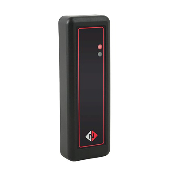
ReadeR WiRing inSTRUCTiOnS
SP1
125kHz reader models with
the following prefixes:
MP1-EM1
MP1-HT1
MP1-DP1
WP1-EM1
WP1-HT1
WP1-DP1
MP1
SP1-EM1
SP1-DP1
SP1-DP1
WP2-EM1
WP2
13.56MHz reader models
with the following prefixes:
MP1-LEG
MP1-MIF
MP1-ISO
DOC0067 Issue 1.0
WP1
WP1-LEG
WP1-MIF
WP1-ISO
Advertisement

Related Manuals for Nortech SP1

Summary of Contents for Nortech SP1
- Page 1 DOC0067 Issue 1.0 ReadeR WiRing inSTRUCTiOnS 125kHz reader models with 13.56MHz reader models the following prefixes: with the following prefixes: MP1-EM1 SP1-EM1 MP1-LEG WP1-LEG MP1-HT1 SP1-DP1 MP1-MIF WP1-MIF MP1-DP1 SP1-DP1 MP1-ISO WP1-ISO WP1-EM1 WP2-EM1 WP1-HT1 WP1-DP1...
- Page 2 125KHz Reader Wiring Connect the reader cable to the reader port of the controller according to the table below. For readers with a screw terminal block, refer to terminal numbering diagram. Terminal* Cable Function *Terminal Numbering +5VDC to +16VDC Black Ground Yellow Green LED input...
- Page 3 13.56MHz Reader Wiring Connect the reader cable to the reader port of the controller according to the table below. For readers with a screw terminal block, refer to terminal numbering diagram. Terminal* Cable Function +5VDC to +16VDC Black Ground White Wiegand Data 1 / Clock Green Wiegand Data 0 / Data...
-
Page 4: Power & Testing
Power & Testing Once the reader is fitted and wired, carry out a brief test to ensure that it is functioning correctly. You may need to refer to the controller reference documentation. Connect power to the controller and ensure that the LED lights red. The reader requires a supply of 5VDC to 16VDC. -
Page 5: Specifications
LED (red/ Green LED, green), Beeper green) Beeper IP Rating IP65 Operating C to 50 Temperature For further details, view or download the corresponding product datasheet from the Nortech website at: http://www.nortechcontrol.com/document-library.aspx Product mounting templates are also available at this location. - Page 6 ReadeR FiTTing inSTRUCTiOnS Fitting Mullion and Wall Switch Readers For those readers fitted with a cover (MP1 and WP1) ensure that the cover securing screw is not fitted to the base of the reader, and separate the front cover and the reader body as follows: Insert the tip of a terminal screwdriver into the small slot in the base of the cover.
- Page 7 Mounting the Mullion Reader Identify a suitable location for the reader at a convenient height near to the door that it controls. Place the reader on the mounting surface and mark the position of the cable hole. Drill a hole suitable for feeding the cable through.
- Page 8 Mounting the Wall Switch Reader Wall Switch readers are designed to fit to a standard wall switch back box (minimum depth 25mm). The WP1 can also be mounted directly on a wall (see the instructions for fitting a mullion mount reader). If the reader is to be mounted on a back box and is fitted with a cable, feed the cable through the hole in the back box to the controller and terminate the conductors according to the wiring details overleaf.
- Page 9 Fitting The Reader Cover (MP1 and WP1) Once the reader has been fitted and wired, the cover can be fitted as described below (the illustration shows the mullion model but the procedure is the same for the wall switch model). Hook the two tabs at the top of the reader cover over the top of the reader back plate, engaging them with the corresponding slots in the back plate.
- Page 10 Fitting the Slimline Reader Identify a suitable location for the reader at a convenient height near to the door that it controls. Mark out the position of the unit and then drill holes for mounting screws and the cable. Feed the cable through the wall and terminate it either at the access controller or in a suitable terminal box.
Need help?
Do you have a question about the SP1 and is the answer not in the manual?
Questions and answers