
Summary of Contents for aFe Power 51-12032
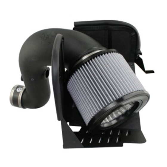
- Page 1 FLOW engineering Instruction Manual P/N: 51-12032 / 54-12032 / 75-12032 & 75-12032-0V Make: Dodge Model: RAM 2500/3500 Year: 2010-2012 Engine: L6-6.7L (td) Cummins...
- Page 2 • Please read the entire instruction manual before proceeding. • Ensure all components listed are present. • If you are missing any of the components, call customer support at 951-493-7100. • Ensure you have all necessary tools before proceeding. • Do not attempt to work on your vehicle when the engine is hot. •...
- Page 3 aFepower.com Page 3...
- Page 4 REMOVAL Figure A Refer to Figure A for Steps 1-2 Step 1: Remove the bolt holding the air box down. 1 Step 2: Disconnect the wiring harness from the Mass air flow sensor and temperture sensor. 2 Page 4...
- Page 5 REMOVAL Figure B Refer to Figure B for Steps 3-4 Step 3: Disconnect the crank case vent line 3 using pliers. Step 4: Loosen the clamp holding the intake tube to the turbocharger 4 and lift the entire intake system out of the vehicle. aFepower.com Page 5...
- Page 6 REMOVAL Figure C Refer to Figure C for Steps 5-6 Step 5: Remove screw that holds the battery mount to the vehicle with a 13mm socket. Step 6: Loosen rear screw that holds the battery mount to the vehicle with a 13mm wrench. Page 6...
- Page 7 INSTALL Figure D Refer to Figure D for Steps 7-9 Step 7: Install supplied trim seal onto your aFe housing Step 8: Place your housing into position like shown while lifting the battery rack tap 8 and slide the mounting tab under the battery rack tab and install and tighten bolts removed in step 5 & 6. Step 9: With the M6 hardware supplied, mount the housing to the radiator mount like shown 9 .
- Page 8 INSTALL Figure E Refer to Figure E for Steps 10-13 Step 10: Remove the Mass air flow sensor and temperature sensor from your oe intake tube and install them to your new aFe intake tube with the gaskets supplied 10 . Step 11: Remove the crank case vent line from your factory intake tube by prying open the metal clamp with a flat blade screwdriver.
- Page 9 INSTALL Figure F Refer to Figure F for Steps 14-15 Step 14: Place the intake tube into position and push the lower tube onto the turbo. Step 15: With the M6 screw and washer, hard-mount the intake tube to the heat shield 13 .
- Page 10 INSTALL Figure G Refer to Figure G for Steps 16-18 Step 16: Tighten both clamps to secure the intake tube to the turbocharger 14 . Step 17: Re-attach the crank case line you removed in step 3 15 . Step 18: Connect the Mass air flow sensor and temperature harnesses. Page 10...
- Page 11 INSTALL Figure H Refer to Figure H for Steps 19-21 Step 19: Install the aFe performance air filter using the supplied clamp. Step 20: Re-connect batteries. Step 21. Verify all connections are secure, your installation is now complete. *Verify all connections are secure 100-200 miles after installation. Page 11...
- Page 12 P/N: 90-59999 P/N: 72-91046 Blue Squeeze Restore Kit Blue Aerosol Restore Kit aFe Key Chain aFe Power Hat P/N: 90-50501 P/N: 90-50001 P/N: 40-10103 P/N: 40-10083 To purchase any of the items above, view airflow charts, dyno graphs, photos, and video; please go to aFepower.com.
-
Page 13: Warranty
Warranty General Terms: • aFe warrants their products to be free from manufacturer’s defects due to workmanship and material. • This warranty applies only to the original purchaser of the product and is non-transferrable. • Proof of purchase of the aFe product is required for all warranty claims. •... - Page 14 Page left blank intentionally Page 14...
- Page 15 Page left blank intentionally Page 15...
- Page 16 advanced FLOW engineering, inc. 252 Granite Street Corona, CA 92879 TEL: 951.493.7100 • TECH: 951.493.7100 x23 E-Mail:Tech@aFepower.com P/N: 06-80408...
Need help?
Do you have a question about the 51-12032 and is the answer not in the manual?
Questions and answers