Table of Contents
Advertisement
Quick Links
Advertisement
Table of Contents
Troubleshooting

Related Manuals for Morita AdvErL EVO


Summary of Contents for Morita AdvErL EVO
- Page 1 Er:YAG Laser for Dentistry AdvErL EVO INSTRUCTIONS FOR USE...
- Page 3 Thank you for purchasing the AdvErL EVO. For optimum safety and performance, read this manual thoroughly before using the unit and pay close attention to the warnings, cautions and notes. Keep this manual in a handy place for ready reference.
-
Page 4: Table Of Contents
Table of Contents Page PREVENT ACCIDENTS ............................4 DISCLAIMER ................................5 1. EQUIPMENT DESCRIPTION ...........................6 2. PARTS IDENTIFICATION AND ACCESSORIES ....................9 (1) Parts Identification.............................9 (2) Accessories .............................. 11 (3) Labels ..............................13 (4) Symbols ..............................14 3. OPERATION ..............................15 (1) Set Up ..............................15 (2) Turn the Unit On............................17 (3) Handpiece and Contact Tip Attachment ....................19 (4) Operation Procedure ..........................21 1) Set Laser Irradiation Conditions .......................21... - Page 5 2.2) Parameter of Laser Ablation ......................53 (3) Warnings and Notes ..........................54 (4) Adverse Effects ............................54 (5) AdvErL EVO INDICATIONS FOR USE ....................54 (6) Clinical Procedure ........................... 55 6.1) General ............................. 55 6.2) Tissue Effects of Er:YAG Laser ....................... 55 6.3) Pulse Energy (Energy Level Setting: mJ) ..................
-
Page 6: Prevent Accidents
PREVENT ACCIDENTS Most operation and maintenance problems result from insufficient attention being paid to basic safety precautions and not being able to foresee the possibilities of accidents. Problems and accidents are best avoided by foreseeing the possibility of danger and operating the unit in accordance with the manufacturer’s recommendations. -
Page 7: Disclaimer
(7) Fires, earthquakes, floods, lightning, natural disasters, or acts of God. • The useful life of the AdvErL EVO is 8 years from the date of installation provided it is regularly and properly inspected and maintained. -
Page 8: Equipment Description
4) Cooling System The AdvErL EVO is water cooled. Water circulates to cool the unit and then the water is cooled by a water-and-air heat exchanger. Water is stored in a tank inside the unit and circulates through the unit. - Page 9 2) When entering the operation area of this equipment, always put on the protective goggles. Furthermore, never allow the laser beam to shine directly on the eyes even if Laser Safety Glasses are worn. 3) Regularly inspect the protective goggles to make sure there are no holes or fine cracks and make sure that they are physically sound.
- Page 10 (5) Measures to prevent fire The heat generated by the laser beam could cause significant fire damage. Make sure the laser beam will not strike any combustible substances within the operation area. (6) Accidental Irradiation Precautions 1) Before performing laser beam emission, living body tissue that could be exposed to laser beam emission should be well-covered with gauze that has been soaked in a saline solution so that it cannot be harmed by accidental laser irradiation.
-
Page 11: Parts Identification And Accessories
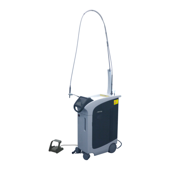
2. Parts Identification and Accessories (1) Parts Identification Main Unit Hollow Waveguide Hollow Waveguide Support Start Switch Upper Tray Handpiece Spray Water Handpiece Connector Hanger Touch Panel Display Rear Handle Front Handle Ventilation Opening Emergency Stop Switch Spray Water Level Window Front Door Foot Switch Brake... - Page 12 Touch Panel Display(Main panel) PPS (pulse per second) Indicator Shows the rate for pulsed irradiation (Unit: PPS). Energy Level Indicator (mJ) Shows the energy level setting (Unit: mJ). Memory Key Use this to memorize and retrieve different sets of irradiation conditions. Water Key Turn the spray on and off.
-
Page 13: Accessories
(2) Accessories Contact Tips C400F (1) C600F (1) C800F (1) S600T (1) PS400TS (2) PS600TS (1) PS600T (1) Laser Safety Glasses Keys (2) Grease Applicator (1) Lens Cleaner (1) (3 pairs) Remote Interlock Tip Stand (1) Foot Switch (1) Hollow Waveguide (1) Connector (1) Hollow Waveguide Power Cord (1) - Page 14 Patient warning plate Operator warning plate Eye warning plate Laser Danger plate Operation Danger plate Optional Tips and Parts CF600 CS600F R135T R200T R300T R600T P400T P600T P400FL PS400T PS800T PS800TS * Only for R135T, R200T and R300T Touch Panel Protective Brush PSM600T R Handpiece Grips...
-
Page 15: Labels
(3) Labels Read All Warning and Caution Labels (inside of the device) Rating Label Instructions for Use 2018-04-23... -
Page 16: Symbols
(4) Symbols * Some symbols may not be used. CE(0197) marking Conforms with the European Directive, 93/42/EEC. Serial number CE marking Conforms with the European Directive, 2011/65/EU. Date of manufacture Manufacturer Attention, consult Refer to instructions for use accompanying documents Marking of electrical equipment in accordance with Type B applied part... -
Page 17: Operation
3. Operation (1) Set Up (1) Put the unit is in position and then step on the tabs to lock the caster brakes. Caster Brakes (2) Take the foot switch off its hook and place it on the floor. Hook (3) Turn on the circuit protector on the back of unit. - Page 18 • When the unit is not in use, always take out the key and give it to the person in charge. • Never use this laser, modify it, or calibrate it in any way other than as described in the user manual. Inadvertent laser emission could be extremely dangerous.
-
Page 19: Turn The Unit On
(2) Turn the Unit On (1) Put on laser safety glasses. (2) Put in the key and turn it to the Stand-by position. (3) Push the Start Switch. Start Switch • The warm-up procedure will run for 20 seconds. * The warm-up countdown number will appear in the operation panel. - Page 20 • A direct, reflected or scattered laser beam can cause permanent blindness. All individuals in the laser use area must wear laser safety glasses supplied with the AdvErL EVO. The Laser safety glasses has an OD of 3.5 (or greater) at 2.94μm. Other parts of the body should also be protected. The laser beam can cause serious injury to the skin and eyes.
-
Page 21: Handpiece And Contact Tip Attachment
(3) Handpiece and Contact Tip Attachment (1) Hold the ring in one hand and then put the handpiece Grips on by turning it until it clicks into place. Handpiece Grips * To remove it, hold the ring and pull it off. Ring ♦... - Page 22 • Tips are sharp and can cause injury; handle them with care. • Use only contact tips specified for use with the AdvErL EVO laser system. • When putting tips on and taking them off, turn the key off or put the unit in standby mode.
-
Page 23: Operation Procedure
(4) Operation Procedure 1) Set Laser Irradiation Conditions (1) Energy Level • Press the “mJ” part of the panel; a window to make this setting will appear. • Press a number to make the setting. • You can also press the plus and minus signs. For less than 100 mJ, values can be set in 5 mJ steps. - Page 24 (4) Turning the Spray Water On and Off Spray Water is emitted from the contact tip to cool the area being irradiated. • Press the Water Key to turn the spray water on and off. • The spray is set for on when the unit is turned on, and the Water Key lights up to show this.
- Page 25 • Take great care when using the tip air inside a body cavity or tubular lumen. Raising the air pressure inside a cavity or lumen could force air into a blood vessel through an open wound and result in a gas embolism.
-
Page 26: Laser Emission Procedure
2) Laser Emission Procedure (1) Press the Ready Key. • The Ready lamp will light up to show that the unit will not emit a laser beam. • The aiming beam will be emitted when you press the Ready Key. (2) Before using the laser, make sure the aiming beam is clear and bright. -
Page 27: Emergency Stop
• The unit will go into Stand-by mode if it passes the automatic self-diagnostic test. Emergency Stop Switch If the unit is not restored to safe and normal operation, or if it will not operate, contact your local dealer or J. MORITA OFFICE. Instructions for Use 2017-06-21... - Page 28 • A direct, reflected or scattered laser beam can cause permanent blindness. All individuals in the laser use area must wear laser safety glasses. Other parts of the body should also be protected. The laser beam can cause serious injury to the skin and eyes. •...
-
Page 29: Memory
4) Memory Twenty combinations of settings can be memorized and retrieved. Press the Memory Key on the Main Panel to show what has been memorized. Memory Display Panel Group Tabs There are 4 groups of memories each of which has 5 sets of memorized settings for a total of 20 sets of settings. - Page 30 Retrieve a Memory (1) Press the Memory key to go to the memory display. (2) Press one of the group tabs. (3) Press a memory number from 1 to 5. Tabs Press the number of the memory (4) This will select the settings for that memory. •...
- Page 31 Memorize New Settings Combination (1) Make the desired settings on the main display. (2) Press the Memory key to go to the memory display. (3) Hold down the Memorize Key for one of the Memory keys for 1 second. (4) A pop-up menu will appear. Press Save Settings. (5) The new setting combination is now memorized.
- Page 32 Change Names of Memories (1) Press the Memory Key to go to the memory display. (2) Hold down the Memorize Key for one of the Memory Keys for 1 second. (3) A pop-up menu will appear. Press Change Name. (4) A keyboard will appear. Enter the name. You may use up to 10 characters.
- Page 33 Change Name of Group Tab Name the tabs for your convenience. (1) Press the Memory Key to go to the memory display. (2) Hold down the tab for one of the groups for 3 seconds. (3) The keyboard will appear. Enter the name. You may use up to 6 characters.
-
Page 34: Turn Unit Off
5) Turn Unit Off (1) Check the unit is in Standby mode. If it is in Ready mode, press the Ready switch. The light inside the Ready Key will go out and the unit will go into Standby mode. (2) Press the Start switch Start Switch The unit will turn off. -
Page 35: Moving The Unit
6) Moving the Unit (1) Hang up the foot switch. (2) Push the handpiece hanger back and put the handpiece in it. 1. Push down the ring on the joint. 2. Push the hanger back. (3) Grip the handle to move the unit. ♦... -
Page 36: Make Other Settings And Check Information
7) Make Other Settings and Check Information Hold down the Menu key. The Menu will appear. Press the key for the category you wish to view. The clock and temperature of the cooling water appear here. Water temperature range for operation: 15 –... - Page 37 Refresh Flash Lamp After considerable use, the flash lamp may no longer work so well and cause errors to occur. This procedure may rectify the problem. It takes about 15 minutes. If the unit is use at low power for a long time, the terminals may get dirty and interfere with ignition.
- Page 38 Show or Hide Log key and Copy Log Use the LOG Button to show or hide the Log key on the main panel. Press “ON” switch to show the Log key. Using the Up and Down, or switch to turn it on or off and then press Enter.
- Page 39 (1) Irradiation Log This shows the irradiation history of the unit. A log entry is created every time the unit emits a laser beam. The log can be copied onto a USB flash drive and used with applications such as Microsoft Excel. The log records up to 1,000 laser emissions.
- Page 40 (2) USB Flash Drives The format for USB flash drive must be at least FAT16/32, 128 Some USB flash drives may not recognize the log data. ♦ Some USB flash drives have a format that will not recognize the data. These can be reformatted using Windows.
- Page 41 • Press the Download key; the data will then be copied onto the USB flash drive. • A progress bar will show how much has been copied so far. • Never unplug the USB flash drive while data is being copied onto it;...
- Page 42 (4) Data Files The data files will be saved in the MEY1LOG folder on the USB flash drive. This folder is created automatically. MEY1LOG Folder and its Contents There is a folder for the year of the records. 2011 (2011, 2012, 2013….) Inside the year folder there are folders for the month of the records.
-
Page 43: Sterilization, Replacement Parts, And Storage
4. Sterilization, Replacement Parts, and Storage • To prevent the spread of serious, life-threatening infections, the handpiece grips and its hanger, tips and tip stand must be cleaned and sterilized between patients. • All the handpiece grips and its hanger, tips and tip stand are delivered in non-sterile condition. Clean and sterilize them prior to initial use. -
Page 44: Handpiece Grips, Hanger, Tips And Tip Stand Cleaning And Sterilization
(1) Handpiece grips, Hanger, Tips and Tip stand Cleaning and Sterilization 1) Cleaning (Always perform this procedure prior to sterilization) The cleaning process is intended to remove blood, protein and other potential contaminants from tips, handpiece grips and hanger. This will not sterilize them. Contamination control should be performed by trained personnel, while wearing protective gear (including masks gloves and shields). -
Page 45: Autoclaving (Sterilization) (Always Perform This Procedure After Cleaning And Before Use)
2) Autoclaving (sterilization) (Always perform this procedure after cleaning and before use) The autoclaving process is intended to destroy infectious microorganisms and pathogens. (1) Put the handpiece grips, hanger and tips in sterilization pouches or the tip stand for autoclaving. ♦... -
Page 46: Cleaning The Main Unit
(2) Cleaning the Main Unit Prevent contagion and contamination by cleaning the unit regularly. Wipe the outside of the main unit with ethanol for disinfection (Ethanol 70 vol% to 80 vol%) or a neutral detergent. Do not use ozone or ultra violet light to disinfect the treatment area. This could damage plastic, rubber or other materials. -
Page 47: Maintenance
(3) Maintenance For optimum performance follow the maintenance procedures described below. 1) Grease Handpiece Grips Grease the handpiece grips everyday before use or after putting it on and taking it off more than 50 times. The O-rings will be damage if they are not properly lubricated and this can lead to water and air leakage inside the handpiece grips. -
Page 48: Lens Cleaning
♦ Use only the special tool provided to clean the drum and ball lenses ♦ If the aiming beam is hazy even after cleaning the drum lenses, these lenses might need to be replaced. In this case, contact your local dealer or J. MORITA OFFICE. Instructions for Use 2018-04-23... -
Page 49: Spray Water Bottle (Distilled Water For Spray) Replacement
3) Spray Water Bottle (Distilled Water for Spray) Replacement Before use, check the level of the spray water bottle. If air gets in the lines when the bottle is replaced, depress the foot switch to its first level to force the air out. ♦... -
Page 50: Storage
(4) Storage Notes on storage (1) After use turn off the key and the circuit protector. (2) Take out the key and give it to the individual responsible for the unit. (3) Lock the casters. (4) Take the contact tip off the handpiece after use and put it in its case to keep it clean. (5) Unit must be level and not subject to vibrations or bumping. -
Page 51: Replacement Parts
See page 34 for how to check the total number of pulses for the flash lamp by using the Menu. * Order parts through your local dealer or J. MORITA OFFICE. Instructions for Use 2018-04-23... -
Page 52: Installation
• Do not pinch your fingers or catch your clothing in the casters when moving the unit. The AdvErL EVO must be installed with a qualified employee or representative; refer to “Installation Instructions” for setup instructions. -
Page 53: Foot Switch
2) Foot Switch Plug the cord for the foot switch into its mate on unit. Make sure it clicks securely into place. * To unplug it, push the lever in to unlock it and then pull it out. ♦ To avoid breaking the cable wire or damaging the connectors, pay attention to the following points: •... -
Page 54: Maintenance, Inspection And Calibration
6. Maintenance, Inspection and Calibration • The equipment must not be taken apart by anyone except for specially trained MORITA service personnel. High voltage circuits inside the unit could cause death by electric shock. For disassembly and servicing, rely only on J. MORITA OFFICE personnel. -
Page 55: Clinical Applications
(1) Introduction The AdvErL EVO Laser System is intended for use only by dentists trained in the safe handling of the laser. Please read and understand this user manual, and use the laser system in vitro prior to using it on patients. -
Page 56: Warnings And Notes
This device is intended for the incision, excision, vaporization, ablation and coagulation of soft tissue in oral and dentistry and for the ablation and vaporization of hard tissue in dentistry. Use of AdvErL EVO is indicated for: Hard Tissue • Caries removal •... -
Page 57: Clinical Procedure
(6) Clinical Procedure 6.1) General Begin treatment with the lowest energy possible. If more tissue reaction is desired, increase the energy level in small increments until the desired tissue effect is observed. Stop frequently to observe the treated area and adjust the laser settings accordingly. Patients will usually respond more favorably if lower settings are used in the beginning of the treatment. - Page 58 • Tips are sharp and can cause injury; handle them with care. • Use only contact tips specified for use with the AdvErL EVO laser system. • When putting tips on and taking them off, turn the key off or put the unit in standby mode.
-
Page 59: Type Of Tips
6.6) Type of Tips Diameter Series Type Outline End Shape Tissue Type Remarks (μm) C Series Hard Tissue C400F FLAT Perio Hard Tissue C600F FLAT Perio Hard Tissue C800F FLAT Perio P Series Hard Tissue P400FL FLAT Perio Hard Tissue P400T TAPER Perio... - Page 60 Diameter Series Type Outline End Shape Tissue Type Remarks (μm) S Series (SURGICAL TIP) S600T TAPER Soft Tissue R Series R135T TAPER Hard Tissue R200T TAPER Hard Tissue R300T TAPER Hard Tissue R600T TAPER Perio BRUSH TIP Hard Tissue BRUSH FLAT 135×19 Perio...
-
Page 61: Troubleshooting
Explanation of Error and Caution Messages Error and caution messages appear in the touch panel display. Follow the instructions which appear. Contact your local dealer or J. MORITA OFFICE in the following cases: • Repairs are required • Replacement of parts such as the flash lamp, cooling water, deionization filter cartridge etc. - Page 62 Watch Dog Timer activated. Response: Restart the unit. If this does not Watch Dog Timer work, contact your local dealer or J. MORITA OFFICE. A switch error was detected when the unit was The foot switch is turned on.
- Page 63 Laser output does not match set value. This happens if the Response: Restart the unit. If this does not laser has not been Laser output too high work, contact your local dealer or J. MORITA calibrated for some OFFICE. time. Sudden deviation of laser output.
-
Page 64: Troubleshooting For Problems Other Than Error Messages
Troubleshooting for Problems Other than Error Messages. If the procedures described below do not solve the problem, please contact your local dealer or J. MORITA OFFICE. Problem Cause Response Circuit Protector may be Check the Circuit breaker, on the back of the unit. It may Does not turn on. - Page 65 If the cooling water is cloudy or otherwise degraded, replace the cooling water without turning the unit on. Otherwise, the laser emitter could malfunction. Contact your local dealer or J. MORITA CORP for instructions on how to replace the cooling The cooling water Water quality has been water.
- Page 66 Problem Cause Response Fluorescent lights in Plug the unit into another receptacle. • the room flicker The main power source Plug the fluorescent light into another receptacle. • when the laser beam may not be good enough. Use separate circuits for the laser unit and the lights. •...
-
Page 67: Technical Description
9. Technical Description Name AdvErL EVO Model MEY-1-A Type EX-2 Rating AC 100 V to 240 V ±10% Frequency 50/60 Hz Power Consumption 1.5 kVA Electric Shock Protection Class Class I Electric Shock Protection Type Type B with applied component Laser Classification Class 4 <... - Page 68 AdvErL EVO may be repaired and serviced by: • The technicians of J. MORITA’s subsidiaries all over the world. • Technicians employed by authorized J. MORITA dealers and specially trained by J. MORITA. • Independent technicians specially trained and authorized by J. MORITA.
-
Page 69: Electromagnetic Disturbances (Emd)
EMD information provided in the ACCOMPANYING DOCUMENTS. • Use of parts other than those accompanied or specified by J. MORITA MFG. CORP. could result in increased electromagnetic emissions or decreased electromagnetic immunity of this device and result in improper operation. - Page 70 Guidance and Manufacturer’s Declaration – Electromagnetic Immunity This device is intended for use in the electromagnetic environment specified below. The customer or the user of this device should assure that it is used in such an environment. Electromagnetic Immunity Test IEC 60601 Test Level Compliance Level Environment –...
- Page 71 Guidance and Manufacturer’s Declaration – Electromagnetic Immunity This device is intended for use in the electromagnetic environment specified below. The customer or the user of this device should assure that it is used in such an environment. Immunity IEC 60601 Electromagnetic Environment –...
- Page 72 Essential Performance • Laser output level shall be within ±20% / -30% of output set level. • No loss of operation and control of the unit • No operation mode change (change to safe side is acceptable) • No back up data destruction If the essential performance is lost or degraded due to electromagnetic disturbance, unexpected operation mode change or error will be occurred.
- Page 73 Memo...
- Page 74 Memo...
- Page 75 Memo...
- Page 76 Pub. No.: T7026-EN-8 Printed in Japan...
Need help?
Do you have a question about the AdvErL EVO and is the answer not in the manual?
Questions and answers