Table of Contents
Advertisement
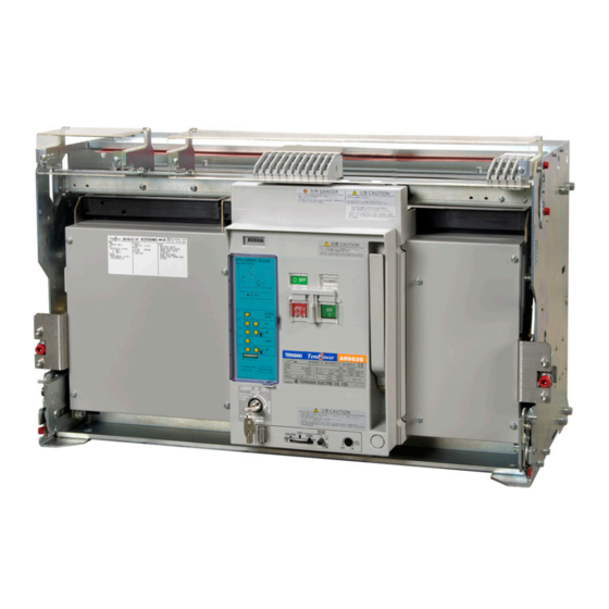
INSTRUCTION MANUAL FOR AIR CIRCUIT BREAKERS
(With Draw-out Cradle and Type AGR-11B Overcurrent Protective Device)
AR650S,AR663S,AR663H
Types:
Notice
Be sure to read this manual before installing, operating, servicing, or inspecting the ACB.
Please retain this manual for future reference.
Electrical work must be done by competent persons.
ACB maintenance, inspection, parts replacement, OCR field tests and setting changes must be
performed by competent persons.
KRB-5331g
Advertisement
Table of Contents


Need help?
Do you have a question about the TemPower AR650S and is the answer not in the manual?
Questions and answers